background image

Chapter 2: Server Installation

2-7

2-6

S

UPER

S

TORAGE

S

YSTEM 6038R-E1CR16L User's Manual

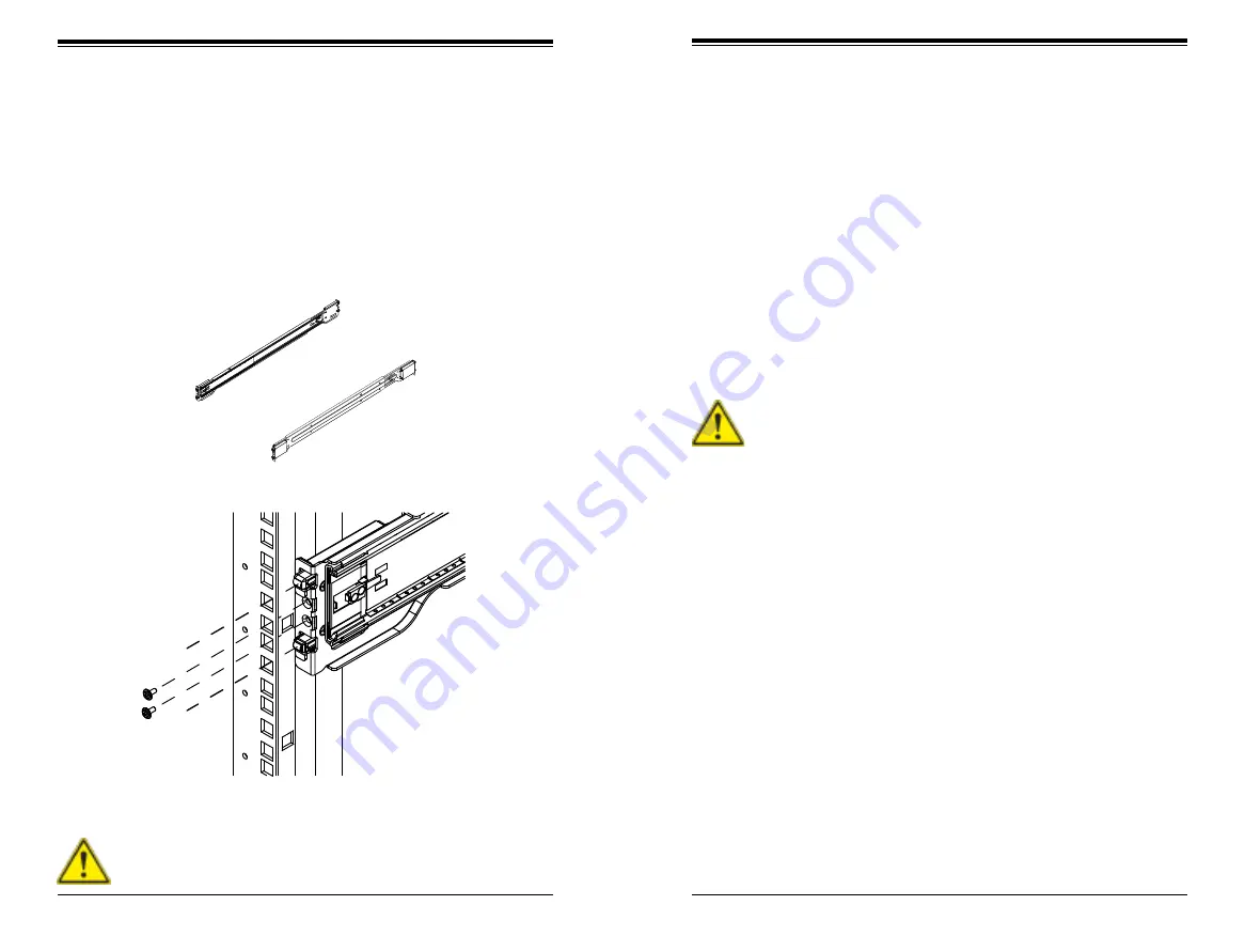
Figure 2-3.  Outer Rails

Figure 2-4.  Installing  the Outer Rails

Installing the Outer (Rack) Rails

Outer rails attach to the server rack and hold the server in place. The outer rails 
for the chassis extend between 30 inches and 33 inches.

Installing the Outer Rails

1.  Attach the right outer rail to the rack by inserting the hooks included on the 

rails into the holes provided on the rack. 

2.  If desired, screw the rails to the chassis for added support.

3.  Repeat these steps for the left outer rail.

Stability hazard. The rack stabilizing mechanism must be in place, or the 
rack must be bolted to the floor before you slide the unit out for servicing. 
Failure to stabilize the rack can cause the rack to tip over.

Slide rail mounted equipment is not to be used as a shelf or a work space.

Installing the Sytem into a Rack

Installing into a Rack

1.  Confirm that the inner and outer rails are properly installed.

2.  Line up the inner (chassis) rails with the front of the outer (rack) rails.

3.  Slide the chassis rails into the rack rails, keeping the pressure even on both 

sides (you may have to depress the locking tabs when inserting). When the 
server has been pushed completely into the rack, you should hear the locking 
tabs "click" into position. 

4.  (Optional) Insert and tighten the thumbscrews that hold the front of the server 

to the rack.

Summary of Contents for SuperStorageSystem 6038R-E1CR16L

Page 1: ...SuperStorageSystem 6038R E1CR16L USER S MANUAL 1 0a ...

Page 2: ...ed except as expressly permitted by the terms of said license IN NO EVENT WILL SUPERMICRO BE LIABLE FOR DIRECT INDIRECT SPECIAL INCIDENTAL SPECULATIVE OR CONSEQUENTIAL DAMAGES ARISING FROM THE USE OR INABILITY TO USE THIS PRODUCT OR DOCUMENTATION EVEN IF ADVISED OF THE POSSIBILITY OF SUCH DAMAGES IN PARTICULAR SUPERMICRO SHALL NOT HAVE LIABILITY FOR ANY HARDWARE SOFTWARE OR DATA STORED OR USED WIT...

Page 3: ... should follow the procedures given in this chapter when installing removing or reconfiguring SAS SATA drives and when replacing system power supply units and cooling fans Chapter 7 BIOS The BIOS chapter includes an introduction to BIOS and provides detailed informa tion on running the CMOS Setup Utility Appendix A BIOS Error Beep Codes Appendix B System Specifications Preface v SUPERSTORAGESYSTEM...

Page 4: ...ter 3 System Interface 3 1 Overview 3 1 vii 3 2 Control Panel Buttons 3 1 Reset 3 1 Power 3 1 3 3 Control Panel LEDs 3 2 Information LED 3 2 Power 3 2 Power Fail 3 3 NIC2 3 3 NIC1 3 3 HDD 3 3 3 4 Drive Carrier LEDs 3 4 Chapter 4 Standardized Warning Statements for AC Systems 4 1 About Standardized Warning Statements 4 1 Warning Definition 4 1 Installation Instructions 4 4 Circuit Breaker 4 5 Power...

Page 5: ... 5 Air Shroud 6 5 6 6 Drive Bay Installation Removal 6 6 Accessing the Drive Bays 6 6 SATA Drive Installation 6 6 Hard Drive Backplane 6 8 6 7 Power Supply 6 9 Power Supply Failure 6 9 Removing Replacing the Power Supply 6 9 Replacing the Power Distributor 6 10 6 8 Attaching a JBOD Expansion Chassis 6 11 Chapter 7 BIOS 7 1 Introduction 7 1 Starting BIOS Setup Utility 7 1 How To Change the Configur...

Page 6: ...SUPERSTORAGESYSTEM 6038R E1CR16L User s Manual x Notes ...

Page 7: ... fans FAN 0125L4 One air shroud MCP 310 39001 0N 12 Gb s IT mode disk controller AOC S3008L L8E JBOD expansion port AOM SAS3 8I8E LP SAS SATA Accessories One SAS SATA backplane BPN SAS3 836EL1 Sixteen 3 5 drive carriers MCP 220 00075 0B One set of mounting rails MCP 290 00053 0N Note For your system to work properly please follow the links below to download all necessary drivers utilities and the ...

Page 8: ...ar I O Ports The I O ports include one COM port a VGA port four USB two USB 3 0 and two USB 2 0 two 10G TLAN Ethernet ports a dedicated IPMI LAN port and dual JBOD expansion ports A UID Unit Identifier button and LED are also located beside the VGA port Onboard Graphics Graphics are provided by an onboard ASpeed AST 2400 BMC which supports IPMI 1 3 Server Chassis Features The SC836BE1C R920B is an...

Page 9: ... com tw Figure 1 1 Intel C612 Chipset System Block Diagram Note This is a general block diagram Please see Chapter 5 for details SPI LAN3 RGRMII Debug Card FRONT PANEL SYSTEM POWER CTRL FAN SPEED PCI E X1 G2 USB 2 0 X10DRH C i T PCH 612 6 0 Gb S USB 2 0 LPC 1 0 5 4 RTL8211E VB CG 3 2 RJ45 BIOS SPI SPI Temp Sensor EMC1402 1 2 at diff SMBUS TPM HEADER USB 3 0 BIOS HEADER SPI AST2400 BMC RMII NCSI CO...

Page 10: ...1 6 SUPERSTORAGESYSTEM 6038R E1CR16L User s Manual Notes ...

Page 11: ...tlet Read the Rack and Server Precautions in the next section 2 3 Preparing for Setup The box the SuperServer 6038R E1CR16L was shipped in should include two sets of rail assemblies two rail mounting brackets and the mounting screws you will need to install the system into the rack Follow the steps in the order given to complete the installation process in a minimum amount of time Please read this...

Page 12: ... ambient temperature of the room Therefore consideration should be given to installing the equipment in an environment compatible with the manufacturer s maximum rated ambient tempera ture TMRA Reduced Airflow Equipment should be mounted into a rack so that the amount of airflow required for safe operation is not compromised Mechanical Loading Equipment should be mounted into a rack so that a haza...

Page 13: ... Rails 1 Locate the rail assembly in the chassis packaging 2 Extend the rail assembly by pulling it outward 3 Press the quick release tab 4 Separate the inner rail extension from the outer rail assembly Installing the Inner Chassis Rails Installing the Inner Rails 1 Extend the inner rail toward the front of the rail assembly as far as possible then depress the locking tab to pull it completely out...

Page 14: ...ck stabilizing mechanism must be in place or the rack must be bolted to the floor before you slide the unit out for servicing Failure to stabilize the rack can cause the rack to tip over Slide rail mounted equipment is not to be used as a shelf or a work space Installing the Sytem into a Rack Installing into a Rack 1 Confirm that the inner and outer rails are properly installed 2 Line up the inner...

Page 15: ...2 8 SUPERSTORAGESYSTEM 6038R E1CR16L User s Manual Notes ...

Page 16: ...er explains the meanings of all LED indicators and the ap propriate response you may need to take 3 2 Control Panel Buttons There are two push buttons located on the front of the chassis These are in order from left to right a reset button and a power on off button Power The main power switch is used to apply or remove power from the power supply to the server system Turning off system power with ...

Page 17: ...t indicates a fan failure When red continuously it indicates an overheat condition which may be caused by cables obstructing the airflow in the system or the ambient room temperature being too warm Check the routing of the cables and make sure all fans are present and operating normally You should also check to make sure that the chassis covers are installed Finally verify that the heatsinks are i...

Page 18: ...y LED Blue Solid On SAS SATA drive installed Blue Blinking I O activity Status LED Red Solid On Failed drive for SAS SATA with RSTe support Red Blinking at 1 Hz Rebuild drive for SAS SATA with RSTe support Red Blinking with two blinks and one stop at 1 Hz Hot spare for SAS SATA with RSTe support Red On for five seconds then off Power on for SAS SATA with RSTe support Red Blinking at 4 Hz Identify ...

Page 19: ... configuring components in the Supermicro chassis These warnings may also be found on our web site at http www supermicro com about policies safety_information cfm Warning This warning symbol means danger You are in a situation that could cause bodily injury Before you work on any equipment be aware of the hazards involved with electrical circuitry and be familiar with standard practices for preve...

Page 20: ...dures couramment utilisées pour éviter les accidents Pour prendre connaissance des traductions des avertissements figurant dans les consignes de sécurité traduites qui accompagnent cet appareil référez vous au numéro de l instruction situé à la fin de chaque avertissement CONSERVEZ CES INFORMATIONS 안전을 위한 주의사항 경고 이 경고 기호는 위험이 있음을 알려 줍니다 작업자의 신체에 부상을 야기 할 수 있는 상태에 있게 됩니다 모든 장비에 대한 작업을 수행하기 전에 전기회로와...

Page 21: ...systeem op de voedingsbron aansluit サーキッ ト ブレーカー この製品は 短絡 過電流 保護装置がある建物での設置を前提としています 保護装置の定格が250 V 20 Aを超えないこ とを確認下さい Warnung Dieses Produkt ist darauf angewiesen dass im Gebäude ein Kurzschluss bzw Überstromschutz installiert ist Stellen Sie sicher dass der Nennwert der Schutzvorrichtung nicht mehr als 250 V 20 A beträgt Advertencia Este equipo utiliza el sistema de protección contra cortocircuit...

Page 22: ...roleer of het beveiligde aparaat niet groter gedimensioneerd is dan 220V 20A Advertencia El sistema debe ser disconnected de todas las fuentes de energía y del cable eléctrico quitado de los módulos de fuente de alimentación antes de tener acceso el interior del chasis para instalar o para quitar componentes de sistema Attention Le système doit être débranché de toutes les sources de puissance ain...

Page 23: ...ntés אזהרה רש בלבד מוסמך צוות את להחליף להתקין אי הציוד עבור שירות לתת או הציוד والمدربيه و لتزكيب استبدال أو خدمة الجهاس هذا يسمح أن يجب فقط المؤهليه للمىظفيه 경고 훈련을 받고 공인된 기술자만이 이 장비의 설치 교체 또는 서비스를 수행할 수 있습니다 Waarschuwing Deze apparatuur mag alleen worden geïnstalleerd vervangen of hersteld door geschoold en gekwalificeerd personeel Warnung Diese Einheit ist zur Installation in Bereichen mit bes...

Page 24: ... ٍ ف نتركُبها مناطق محظورة تم انىص َمكن ً إن ىل منطقت محظورة فقط استخذاو خالل من خاصت أداة أو ٌ أ نال أخري وسُهت مألما ومفتاح قفم 경고 이 장치는 접근이 제한된 구역에 설치하도록 되어있습니다 특수도구 잠금 장치 및 키 또는 기타 보안 수단을 통해서만 접근 제한 구역에 들어갈 수 있습니다 Waarschuwing Dit apparaat is bedoeld voor installatie in gebieden met een beperkte toegang Toegang tot dergelijke gebieden kunnen alleen verkregen worden door gebruik te maken van sp...

Page 25: ...Cuando el sistema está en funcionamiento el voltaje del plano trasero es peligroso Tenga cuidado cuando lo revise Attention Lorsque le système est en fonctionnement des tensions électriques circulent sur le fond de panier Prendre des précautions lors de la maintenance Warning Hazardous voltage or energy is present on the backplane when the system is operating Use caution when servicing Redundant P...

Page 26: ...יים החשמל לחוקי תואמת להיות חייבת הציוד المعدات تركيب الكهربائية لل يمتثل أن يجب قىاويه والىطىية المحلية المتعلقة بالكهرباء 경고 시스템이 동작 중일 때 후면판 Backplane 에는 위험한 전압이나 에너지가 발생 합니다 서비스 작업 시 주의하십시오 Waarschuwing Een gevaarlijke spanning of energie is aanwezig op de backplane wanneer het systeem in gebruik is Voorzichtigheid is geboden tijdens het onderhoud האחורי בפנל מתח אז הרה במהלך להיזהר יש המערכת ...

Page 27: ...vertencia Los ventiladores podran dar vuelta cuando usted quite ell montaje del ventilador del chasis Mandtenga los dedos los destornilladores y todos los objetos lejos de las aberturas del ventilador Attention Il est possible que les ventilateurs soient toujours en rotation lorsque vous retirerez le bloc ventilateur du châssis Prenez garde à ce que doigts tournevis et autres objets soient éloigné...

Page 28: ...s que tienen UL o CSA se muestra en el código de otros dispositivos eléctricos que los productos designados por Supermicro solamente 電源コードとACアダプター 製品を設置する場合 提供または指定された接続ケーブル 電源コードとACアダプター を使用下さい 他のケーブルやアダプタを使用すると故障や火災の原因になるこ とがあ り ます 電気用品安全法は ULまたはCSA認定のケーブル UL CSEマークがコードに表 記 を Supermicroが指定する製品以外に使用するこ とを禁止しています ומתא חשמליים מ י AC אזהרה ומתאמים ספקים בכבלים להשתמש יש המוצר את מתקינים כאשר AC אשר...

Page 29: ...4 20 SUPERSTORAGESYSTEM 6038R E1CR16L User s Manual Notes ...

Page 30: ...carefully see previous chapter To prevent the serverboard from bending keep one hand under the center of the board to support it when handling The following measures are generally sufficient to protect your equipment from electric static discharge Precautions Use a grounded wrist strap designed to prevent Electrostatic Discharge ESD Touch a grounded metal object before removing any board from its ...

Page 31: ...ee Section 5 9 for power connector pin definitions Connecting the Control Panel JF1 contains header pins for various front control panel connectors See Figure 5 1 for the pin locations of the various front control panel buttons and LED indicators All JF1 wires have been bundled into a single cable to simplify this connection Make sure the red wire plugs into pin 1 as marked on the board The other ...

Page 32: ...When receiving a serverboard without a processor pre installed make sure that the plastic CPU socket cap is in place and none of the socket pins are bent otherwise contact your retailer immediately Refer to the Supermicro web site for updates on CPU support OPEN1st WARNING OPEN1st WARNING Press down on the lever labeled Close 1st Pull lever away from the socket Gently push down to pop the load pla...

Page 33: ...y been applied 2 Place the heatsink on top of the CPU so that the four mounting holes are aligned with those on the serverboard and the heatsink bracket underneath 3 Screw in two diagonal screws i e the 1 and the 2 screws until just snug do not over tighten the screws to avoid possible damage to the CPU 4 Finish the installation by fully tightening all four screws Screw 1 Screw 2 Screw 3 Screw 4 F...

Page 34: ...MMC2 P1 DIMMD2 CPU2 P2 DIMME1 P2 DIMMF1 P2 DIMMG1 P2 DIMMH1 P2 DIMME2 P2 DIMM F2 P2 DIMMG2 P2 DIMMH2 Processor and Memory Module Population for Optimal Performance Number of CPUs DIMMs CPU and Memory Population Configuration Table For memory to work properly please follow this table 1 CPU 2 DIMMs CPU1 P1 DIMMA1 P1 DIMMB1 1 CPU 4 DIMMs CPU1 P1 DIMMA1 P1 DIMMB1 P1 DIMMC1 P1 DIMMD1 1 CPU 6 or 8 DIMMs...

Page 35: ...sh by using a screw to secure the top of the card shield to the chassis The PCI slot shields protect the serverboard and its components from EMI and aid in proper ventilation so make sure there is always a shield covering each unused slot BIOS LICENSE MAC CODE BAR CODE X10DRH C i T Rev 1 00 BIOS LICENSE MAC CODE BAR CODE X10DRH C i T Rev 1 00 6 5 BIOS LICENSE MAC CODE BAR CODE X10DRH C i T Rev 1 0...

Page 36: ...rs JSTBY1 Standby Power Connector JTPM1 TPM Trusted Platform Module Port 80 Header LAN1 LAN2 10G bit Ethernet TLAN Ports IPMI_LAN Dedicated IPMI LAN supported by the ASpeed controller I SATA 0 5 SATA 3 0 Ports supported by Intel PCH S SATA SATA 3 0 4 port Vertical Connector supported by Intel SCU I SGPIO1 2 Serial Link General Purpose I O Headers UID UID Unit Identification Button USB 0 1 2 0 USB ...

Page 37: ...s JPWR1 JPWR2 must be connected to the power supplyto pro vide adequate power to the system These power connectors meet the SSI EPS 12V specification See the table on the right for pin definitions Overheat Fan Power Fail UID LED Connect an LED cable to pins 7 and 8 of the front control panel to use the Overheat Fan Fail Power Fail and UID LED connections The red LED on pin 8 provides warnings of o...

Page 38: ...tion 1 Intrusion Input 2 Ground Power LED Speaker On the JD1 header pins 1 3 are for a power LED and pins 4 7 are for the speaker Close pins 4 7 with a jumper to use an external speaker If you wish to use the onboard speaker please close pins 6 7 See the table on the right for speaker pin definitions Internal Speaker The internal speaker located at SP1 can be used to provide audible indica tions f...

Page 39: ...ch again to turn off the LED indicators These indicators provide easy identification of a system unit that may be in need of service Note UID can also be triggered via IPMI For more information on IPMI please refer to the IPMI User s Guide posted on our website at http www supermicro com UID Switch Pin Definition 1 Ground 2 Ground 3 Button In 4 Button In UID LED Status Color State Status Blue On U...

Page 40: ...n means the jumper is either on only one pin or completely removed Connector Pins Jumper Setting 3 2 1 3 2 1 CMOS Clear JBT1 is used to clear CMOS which will also clear any passwords Instead of pins this jumper consists of contact pads to prevent accidentally clearing the contents of CMOS To clear CMOS 1 First power down the system and unplug the power cord s 2 With the power disconnected short th...

Page 41: ...he right for jumper settings BMC Enable Jumper Settings Jumper Setting Definition Pins 1 2 Enabled Pins 2 3 Disabled ME Mode Select Jumper Settings Jumper Setting Definition Pins 1 2 Normal Pins 2 3 Manufacture s Mode Manufacturer s Mode Jumper JPME2 allows the user to flash the system firmware from a host server in order to modify system settings Close this jumper to bypass SPI flash security and...

Page 42: ...ity while the green LED on the left indicates the speed of the connection See the table at right for more information BMC Heartbeat LED A BMC Heartbeat LED is located at LEDM1 on the serverboard When blinking the BMC is functioning nor mally IPMI LAN Link LED Left Activity LED Right Color State Definition Link Left Green Solid 100 Mbps Amber Solid 1 Gbps Activity Right Amber Blinking Active Onboar...

Page 43: ...o install each item from top to the bottom one at a time After installing each item you must re boot the system before moving on to the next item on the list The bottom icon with a CD on it allows you to view the entire contents SuperDoctor 5 The Supermicro SuperDoctor 5 is a program that functions in a command line or web based interface in Windows and Linux operating systems The program moni tor...

Page 44: ...ccur if this practice is not strictly followed Figure 5 8 Installing the Onboard Battery OR Please handle used batteries carefully Do not damage the battery in any way a damaged battery may release hazardous materials into the environment Do not discard a used battery in the garbage or a public landfill Please comply with the regulations set up by your local hazardous waste management agency to di...

Page 45: ...To prevent damage to any printed circuit boards PCBs it is important to handle them very carefully The following measures are generally sufficient to protect your equipment from ESD damage Precautions Use a grounded wrist strap designed to prevent static discharge Touch a grounded metal object before removing any board from its antistatic bag Handle a board by its edges only do not touch its compo...

Page 46: ... and Rear Chassis Views 6 2 Control Panel The control panel on the front of the chassis connects to the JF1 connector on the serverboard to provide you with system status indications A ribbon cable has bundled these wires together to simplify the connection The LEDs inform you of system status See Chapter 3 for details on the LEDs and the control panel buttons Details on JF1 can be found in Chapte...

Page 47: ...hroud 6 5 Air Shroud Air shrouds concentrate airflow to maximize fan efficiency The SC836 chassis air shroud does not require screws to set up Air Shroud Installation 1 Remove the chassis cover If necessary remove the rear fans 2 Place the air shroud in the chassis as illustrated The shroud aligns with the fan holders and sits behind two of the front fans covers two of the rear fans Make sure the ...

Page 48: ...rage SAS 1 CompList 110909 pdf SATA Drive Installation These drives are mounted in carriers to simplify their installation and removal from the chassis The carriers also help promote proper airflow for the drives For this reason even empty carriers without hard drives installed must remain in the chassis Removing a Drive Carrier 1 Push the release button located beside the drive s LEDs 2 Swing the...

Page 49: ...ating If either of the two power supply modules fail the other module will take the full load and allow the system to continue operation without interruption The Power Fail LED on the front control panel will illuminate and remain on until the failed unit has been replaced Replacement units can be ordered directly from Supermicro The power supply units have a hot swap capability meaning you can re...

Page 50: ... from the chassis 3 Locate the power distributor between the power supply and the fan row 4 Remove the three screws securing the power supply 5 Gently pull the power distributor from the chassis Make sure to guide all the cables through the power distributor housing 6 Slide the new power distributor module into the power distributor housing Make that you slide the cables through the bottom of the ...

Page 51: ...6 12 SUPERSTORAGESYSTEM 6038R E1CR16L User s Manual JBOD OUT downstream ports Note the use of two cables 8x SAS lanes is recommended Figure 6 9 JBOD Expansion ...

Page 52: ...can be configured by the user The right frame displays the key legend Above the key legend is an area reserved for a text message When an option is selected in the left frame it is highlighted in white Often a text message will accompany it Note the AMI BIOS has default text messages built in Supermicro retains the option to include omit or change any of these text messages The AMI BIOS setup util...

Page 53: ...the memory modules installed in the system How to Start the Setup Utility Normally the only visible Power On Self Test POST routine is the memory test As the memory is being tested press the Delete key to enter the main menu of the AMI BIOS setup utility From the main menu you can access the other setup screens An AMI BIOS identification string is displayed at the left bottom corner of the screen ...

Page 54: ...e Interrupt 19 at bootup immediately and allow the drives that are attached to the host adap tors to function as bootable disks If this item is set to Postponed the ROM BIOS of the host adaptors will not capture Interrupt 19 immediately to allow the drives attached to the adaptors to function as bootable devices at bootup The options are Immediate and Postponed Re try Boot Select EFI Boot to allow...

Page 55: ...nd Disable Direct Cache Access DCA Select Enable to use Intel DCA Direct Cache Access Technology to improve the efficiency of data transferring and accessing The options are Auto Enable and Disable X2 APIC Advanced Programmable Interrupt Controller Based on Intel s Hyper Threading architecture each logical processor thread is assigned 256 APIC IDs APIDs in 8 bit bandwidth When this feature is set ...

Page 56: ...are components only Select SW_ALL to change the P state coordination type for all software installed in the system Select SW_ANY to change the P state coordination type for a soft ware program in the system The options are HW_All SW_ALL and SW_ANY CPU C State Control Available when Power Technology is set to Custom Package C State limit Use this item to set the limit on the C State package registe...

Page 57: ...h its frequency and voltage scaled back a notch The options are Between P1 P0 and Below P1 DRAM RAPL Running Average Power Limit Configuration DRAM RAPL Running Average Power Limit Baseline Use this item to set the run time power limit baseline for DRAM modules The options are Disable DRAM RAPL Mode 0 and DRAM RAPL Mode 1 Override BW_LIMIT_TF BW_limit_tf This feature allows the user to turn off th...

Page 58: ...error logic for the port specified by the user The options are Disable and Enable Corr Err Correctable Error Over Select Enable to force correctable error prorogation to the IIIO core error logic for the port specified by the user The options are Disable and Enable L0s Support When this item is set to Disable IIO will not put its transmitter in the L0s state The default setting is Disable Socket 0...

Page 59: ...3 Generation 3 DN TX Preset Use this item to set the Preset mode for PCI E Gen3 downstream transmit ting TX from the master device to a slave device The options are Auto P0 6 0 0 0 dB P1 3 5 0 0 dB P2 4 5 0 0 dB P3 2 5 0 0 dB P4 0 0 0 0 dB P5 0 0 2 0 dB P6 0 0 2 5 dB P7 6 0 3 5 dB P8 3 5 3 5 dB and P9 0 0 3 5 dB Gen3 Generation 3 DN RX Preset Hint Use this item to set the Preset Hint mode for PCI ...

Page 60: ...gth of time required for the port specified by the user to complete the transition from L1 to L0 The default setting is 1uS 1uS 2uS 2uS 4uS 4uS 8uS 8uS 16uS 16uS 32uS 32uS 64uS and 64uS Fatal Err Error Over Select Enable to force fatal error prorogation to the IIO core error logic for the port specified by the user The options are Disable and Enable Non Fatal Err Error Over Select Enable to force ...

Page 61: ...ther tasks The options are Enable and Disable No Snoop Select Enable to support no snoop mode for each CB device The options are Disable and Enable Relaxed Ordering Select Enable to enable Relaxed Ordering support which will allow certain transactions to violate the strict ordering rules of PCI bus for a transaction to be completed prior to other transactions that have already been enqueued The op...

Page 62: ...AM RAPL Mode 0 and DRAM RAPL Mode 1 Set Throttling Mode Throttling improves CPU reliability and reduces power consumption via automat ic voltage control during CPU idle states The options are Disabled and CLTT Closed Loop Thermal Throttling Socket Interleave Below 4GB Select Enable for the memory above the 4G Address space to be split between two sockets The options are Enable and Disable A7 Mode ...

Page 63: ...all USB devices available for EFI applications only The options are Enabled Disabled and Auto XHCI Hand Off This is a work around solution for operating systems that do not support XHCI Ex tensible Host Controller Interface hand off The XHCI ownership change should be claimed by the XHCI driver The settings are Enabled and Disabled EHCI Hand Off This item is for operating systems that do not suppo...

Page 64: ...rt specified by the user should be con nected to a Solid State drive or a Hard Disk Drive The options are Hard Disk Drive and Solid State Drive If the item above Configure SATA as is set to IDE the following items will display SATA Port 0 Port 5 This item displays the information of a SATA device installed on the SATA port specified by the user Software Preserve SATA Device Type Available when a S...

Page 65: ...ber of drive and capacity sSATA Port 0 Port 3 Select Enabled to enable an sSATA port specified by the user The options are Disabled and Enabled Spin Up Device On an edge detect from 0 to 1 set this item to allow the PCH to start a COMRE SET initialization to the device The options are Enabled and Disabled Device Type Use this item to specify if the sSATA port specified by the user should be con ne...

Page 66: ... to allow a PCI device to generate a PERR PCI PCI E Parity Error number for a PCI bus error event The options are Enabled and Disabled SERR Generation Select Enabled to allow a PCI device to generate an SERR System Error number for a PCI bus error event The options are Enabled and Disabled PCI PERR SERR Support Select Enabled to support PERR PCI PCI E Parity Error SERR System Error runtime error r...

Page 67: ...ible Firmware Interface for network stack support The options are Enabled and Disabled Super IO Configuration Super IO Chip AST2400 Serial Port 1 Configuration Serial Port 2 Configuration Serial Port 1 Serial Port 2 Select Enabled to enable the onboard serial port specified by the user The options are Enabled and Disabled Device Settings This item displays the base I O port address and the Interru...

Page 68: ... packet Select 1 Stop Bit for standard serial data communication Select 2 Stop Bits if slower devices are used The options are 1 and 2 Flow Control Use this item to set the flow control for Console Redirection to prevent data loss caused by buffer overflow Send a Stop signal to stop sending data when the receiving buffer is full Send a Start signal to start sending data when the receiving buffer i...

Page 69: ...options are 1 and 2 Flow Control Use this feature to set the flow control for Console Redirection to prevent data loss caused by buffer overflow Send a Stop signal to stop sending data when the receiving buffer is full Send a Start signal to start data sending when the receiving buffer is empty The options are None and Hardware RTS CTS VT UTF8 Combo Key Support Select Enabled to enable VT UTF8 Com...

Page 70: ... Redirec tion Make sure that the same speed is used in both host computer and the client computer A lower transmission speed may be required for long and busy lines The options are 9600 19200 57600 and 115200 bits per second Flow Control Use this item to set the flow control for Console Redirection to prevent data loss caused by buffer overflow Send a Stop signal to stop data sending when the rece...

Page 71: ...feature Select Enabled to enable Non Uniform Memory Access support to enhance system performance The options are Enabled and Disabled iSCSI Configuration This item displays iSCSI configuration information iSCSI Initiator Name Use this item to enter the name of the iSCSI Initiator which is a unique name used in the world The name must in the IQN format The following submenu will be available for co...

Page 72: ... to do nothing when the SMBIOS event log is full The options are Do Nothing and Erase Immediately SMBIOS Event Log Standard Settings Log System Boot Event Select Enabled to log system boot events The options are Disabled and Enabled MECI Multiple Event Count Increment Enter the increment value for the multiple event counter Enter a number between 1 to 255 The default setting is 1 METW Multiple Eve...

Page 73: ...ally reset the following IPMI settings upon next system boot The options are Yes and No Configuration Address Source Available when the item above Update IPMI LAN Configuration is set to Yes Use this item to select the IP address source for this computer If Static is selected you will need to know the IP address of this computer and enter it to the system manually in the field If DHCP is selected ...

Page 74: ...r to configure Boot settings for this system Boot Configuration Boot Mode Select Use this item to select the type of device to be used for system boot The options are Legacy UEFI and Dual Fixed Boot Order Priorities This option prioritizes the order of bootable devices from which the system will boot Press Enter on each entry from top to bottom to select devices When the item above Boot Mode Selec...

Page 75: ... manufacture default settings which are designed for maximum system performance but not for maximum stability Save As User Defaults Select this item and press Enter to save the current BIOS settings as user s default settings for future use Restore User Defaults Select this item and press Enter to retrieve the user defined default settings that were previously saved to be used as current default s...

Page 76: ...7 48 SUPERSTORAGESYSTEM 6038R E1CR16L User s Manual Notes ...

Page 77: ...l errors are usually communicated through a series of audible beeps The numbers on the fatal error list correspond to the number of beeps for the cor responding error Motherboard BIOS Error Beep Codes Beep Code LED Error Message Description 1 beep Refresh Ready to boot 5 short beeps 1 long beep Memory error No memory detected in the system 5 beeps No con in or con out devices Con in includes USB o...

Page 78: ...A 2 SUPERSTORAGESYSTEM 6038R E1CR16L User s Manual Notes ...

Page 79: ...IMM sockets supporting up to 2 TB of ECC LRDIMM Load Reduced DIMMs or 1 TB of ECC RDIMM Registered DIMMs DDR4 2400 2133 1866 1600 memory Note see Section 5 6 for details Drive Bays Sixteen hot swap drive bays to house sixteen SATA drives Expansion Slots Six PCI Express 3 0 x8 slots and one PCI Express 3 0 x16 slot Serverboard X10DRH iT Extended ATX form factor Dimensions 13 68 x 13 05 in 347 5 x 3...

Page 80: ... 60950 1 Compliant UL or CSA Listed USA and Canada CE Marking Europe California Best Management Practices Regulations for Perchlorate Materials This Perchlorate warning applies only to products containing CR Manganese Dioxide Lithium coin cells Perchlorate Material special handling may apply See www dtsc ca gov hazardouswaste perchlorate continued from front The products sold by Supermicro are not...

Page 81: ...B 4 SUPERSTORAGESYSTEM 6038R E1CR16L User s Manual Notes ...

Reviews: