background image

Chapter 5: Advanced Serverboard Setup

5-7

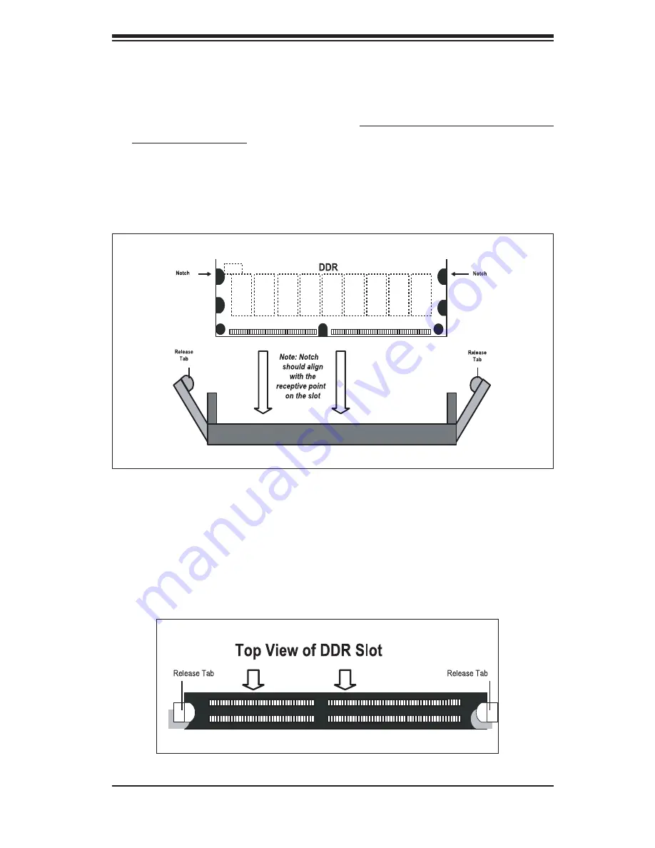
Figure 5-5b.  Top View of DDR Slot 

Figure 5-5a. Installing DIMM into Slot

To Install: Insert module vertically and press down until it snaps into place.  Pay attention 

to 

the 

bottom 

notch. 


To Remove: Use your thumbs to gently push each release tab outward to free the DIMM 

from the slot.

Memory Support

The  X6DVA-4G  supports  up  to  24  GB  of  registered  ECC  DDR266  or  up  to  12 

GB of registered ECC DDR333 SDRAM.  You should not mix DIMMs of differ-

ent sizes and speeds.  See Figures 5-5a and 5-5b for installing and removing 

memory modules.

Summary of Contents for SUPERSERVER 6014V-M4

Page 1: ...SUPER SUPERSERVER 6014V M4 USER S MANUAL Revision 1 0a...

Page 2: ...R INABILITY TO USE THIS PRODUCT OR DOCUMENTATION EVEN IF ADVISED OF THE POSSIBILITY OF SUCH DAMAGES IN PARTICULAR THE VENDOR SHALL NOT HAVE LIABILITY FOR ANY HARDWARE SOFTWARE OR DATA STORED OR USED W...

Page 3: ...st chapter provides a checklist of the main components included with the server system and describes the main features of the Super X6DVA 4G serverboard and the SC813MS 420C chassis Chapter 2 Server I...

Page 4: ...or removing processors or main memory and when recon g uring the serverboard Chapter 6 Advanced Chassis Setup Refer to Chapter 6 for detailed information on the SC813MS 420C 1U rackmount server chass...

Page 5: ...v Preface Notes...

Page 6: ...Precautions 2 2 Rack Mounting Considerations 2 3 2 4 Installing the System into a Rack 2 4 Identifying the Sections of the Rack Rails 2 4 Installing the Rear Inner Rails 2 4 Installing the Rack Rails...

Page 7: ...r Cables 5 4 Connecting the Control Panel 5 5 5 4 I O Ports 5 6 5 5 Installing Memory 5 6 5 6 Adding PCI Cards 5 8 5 7 Serverboard Details 5 9 Super X6DVA 4G Layout 5 9 X6DVA 4G Quick Reference 5 10 5...

Page 8: ...et 5 19 Power Force On 5 19 Watch Dog Enable Disable 5 20 5 10 Onboard Indicators 5 20 JLAN1 JLAN2 LEDs 5 20 SATA LED Header 5 21 Onboard LED Indicators 5 21 System LED 5 21 5 11 SCSI and IDE Hard Dri...

Page 9: ...Introduction 7 1 7 2 Main Setup 7 2 7 3 Advanced Settings 7 3 7 4 Boot Settings 7 16 7 5 Security Settings 7 19 7 6 Exit Options 7 20 Appendices Appendix A BIOS Error Beep Codes A 1 Appendix B BIOS PO...

Page 10: ...x Notes SUPERSERVER 6014V M4 User s Manual...

Page 11: ...components may have been included with the 6014V M4 as listed below One 1 slim CD ROM drive CSE TEAC 24 B SCSI Accessories Four 4 SCA SCSI hard drive carriers CSE PT 39 B One 1 SCSI backplane CSE SCA...

Page 12: ...l memory modules used to populate the system should be the same size type and speed SCSI Subsystem The onboard LSI 53C1020 single channel SCSI controller supports four 80 pin SCA Ultra320 SCSI hard dr...

Page 13: ...nboard I O backpanel ports include one COM port a VGA port two USB ports PS 2 mouse and keyboard ports and two GLAN NIC ports Other Features Other onboard features that promote system health include v...

Page 14: ...ure 1 1 Intel E7320 Chipset System Block Diagram Note This is a general block diagram Please see Chapter 5 for details Mouse Keyboard Flpy Prntr COM1 FPUSB FPUSB USB USB SATA SATA IDE IDE Video SRAM P...

Page 15: ...ot swap capability of the SCSI drives Control Panel The SC813MS 420C s control panel provides important system monitoring and control information LEDs indicate power on network activity hard disk driv...

Page 16: ...ling design that features four 4 cm high performance system cooling fans Each of these fans plug into a chassis fan header on the serverboard A fan speed control setting in BIOS allows fan speed to be...

Page 17: ...s SuperMicro Computer B V Het Sterrenbeeld 28 5215 ML s Hertogenbosch The Netherlands Tel 31 0 73 6400390 Fax 31 0 73 6416525 Email sales supermicro nl General Information support supermicro nl Techni...

Page 18: ...1 8 SUPERSERVER 6014V M4 User s Manual Notes...

Page 19: ...damaged in any way If the server itself shows damage you should le a damage claim with the carrier who delivered it Decide on a suitable location for the rack unit that will hold the SuperServer 6014V...

Page 20: ...d be coupled together Always make sure the rack is stable before extending a component from the rack You should extend only one component at a time extending two or more simultaneously may cause the r...

Page 21: ...mised Mechanical Loading Equipment should be mounted into a rack so that a hazardous condition does not arise due to uneven mechanical loading Circuit Overloading Consideration should be given to the...

Page 22: ...hind the preinstalled front inner rails Note that these two rails are left right speci c Installing the Rear Inner Rails First locate the right rear inner rail the rail that will be used on the right...

Page 23: ...on the chassis rail guides at the desired location in the rack keeping the sliding rail guide facing the inside of the rack Screw the assembly securely to the rack using the brackets provided Attach t...

Page 24: ...e server into the rack Do this by lining up the rear of the chassis rails with the front of the rack rails Slide the chassis rails into the rack rails keeping the pressure even on both sides you may h...

Page 25: ...Telco Rack If you are installing the SuperServer 6014V M4 into a Telco type rack follow the di rections given on the previous pages for rack installation The only difference in the installation proce...

Page 26: ...e of the server 2 Check the CPU processor You may have one or two processors already installed into the system board Each processor should have its own heatsink attached See Chapter 5 for instructions...

Page 27: ...Chapter 2 Server Installation 2 9 Figure 2 4 Accessing the Inside of the SuperServer 6014V M4...

Page 28: ...r system s con guration your system may have one or more SCSI drives already installed If you need to install SCSI drives please refer to the appropriate section in Chapter 6 4 Check the air ow Air ow...

Page 29: ...switch on the power supply This chapter explains the meanings of all LED indicators and the appropriate response you may need to take 3 2 Control Panel Buttons There are two push button buttons locate...

Page 30: ...dition which may be caused by cables obstructing the air ow in the system or the ambient room temperature being too warm Check the routing of the cables and make sure all fans are present and operatin...

Page 31: ...inated the green LED on the front of the SCSI drive car rier indicates drive activity A connection to the SCSI SCA backplane enables this LED to blink on and off when that particular drive is being ac...

Page 32: ...3 4 SUPERSERVER 6014V M4 User s Manual Notes...

Page 33: ...e system with the operating system rst and then unplug the power cords of all the power supply units in the system When working around exposed electrical circuits another person who is familiar with t...

Page 34: ...led into a cooling fan Remove any jewelry or metal objects from your body which are excellent metal conductors that can create short circuits and harm you if they come into contact with printed circui...

Page 35: ...l components and printed circuit boards PCBs in their antistatic bags until ready for use Touch a grounded metal object before removing the board from the antistatic bag Do not let components or PCBs...

Page 36: ...hat the chassis cover is in place when the 6014V M4 is operating to assure proper cooling Out of warranty damage to the 6014V M4 system can occur if this practice is not strictly followed Figure 4 1 I...

Page 37: ...at the size and weight of the serverboard can cause it to bend if handled improperly which may result in damage To prevent the serverboard from bending keep one hand under the center of the board to s...

Page 38: ...essors of up to 3 60 GHz If installing one processor only install it into CPU socket 1 5 2 Processor and Heatsink Installation When handling the processor package avoid placing direct pressure on the...

Page 39: ...er is only partly raised damage to the socket or CPU may result 5 Screw in two diagonal screws until just snug do not fully tighten then do the same with the remaining two diagonal screws Finish by fu...

Page 40: ...connect to the pin 1 locations If you are con guring the system keep the air ow in mind when routing the cables The following data cables with their serverboard connector locations noted should be co...

Page 41: ...of each header All JF1 wires have been bundled into single keyed ribbon cable to simplify their connection The red wire in the ribbon cable plugs into pin 1 of JF1 Connect the other end of the cable...

Page 42: ...damage Also note that the memory is inter leaved to improve performance see step 1 DIMM Installation See Figure 5 5 1 Insert the desired number of DIMMs into the memory slots starting with Bank 1 bot...

Page 43: ...place Pay attention to the bottom notch To Remove Use your thumbs to gently push each release tab outward to free the DIMM from the slot Memory Support The X6DVA 4G supports up to 24 GB of registered...

Page 44: ...X riser ts into the 133 MHz PCI X slot to support a full height half length PCI X add on card at any speed 2 PCI card installation Before installing a PCI add on card see step 1 above Begin by swingin...

Page 45: ...XL 6300ESB ICH PXH BATTERY x4 PCI Express DIMM 1B BANK 1 J4 BIOS JBT1 FAN1 JF1 Speaker DIMM 1A DIMM 2B DIMM 2A DIMM 3B DIMM 3A FAN2 IPMI 100 MHz PCI X 133 MHz PCI X COM2 JLAN1 JLAN2 JPL1 J28 PW3 PW1...

Page 46: ...FAN 1 6 System Fan Headers J2 Keyboard Mouse Ports J4 J5 COM1 COM2 Serial Port Connector Header J10 Parallel Printer Port Header J24 Floppy Disk Drive Connector J28 U320 SCSI Connector J38 IDE 2 Hard...

Page 47: ...e on the right for pin de nitions Secondary Power Connector In addition to the Primary ATX power connector above the Secondary 12v 8 pin PW2 connector must also be connected to your power supply See t...

Page 48: ...es to redundant power supplies and so does not apply to the 6014V M4 NIC2 LED The NIC2 Network Interface Control ler LED connection is located on pins 9 and 10 of JF1 Attach the NIC2 LED cable to disp...

Page 49: ...de depress the button for at least 4 seconds Refer to the table on the right for pin de nitions Universal Serial Bus USB0 1 Two Universal Serial Bus ports are located beside the keyboard mouse ports S...

Page 50: ...accept RJ45 type cables Note Pin 10 is included on the header but not on the port NC indicates no connection Serial Port Pin De nitions J4 J5 Pin De nition Pin De nition 1 CD 6 DSR 2 RD 7 RTS 3 TD 8...

Page 51: ...pin de nitions Front Panel Universal Serial Bus Pin De nitions USB2 3 USB2 Pin De nition USB3 Pin De nition 1 5V 1 5V 2 PO 2 PO 3 PO 3 PO 4 Ground 4 Ground 5 Key 5 No connection Power LED Speaker On...

Page 52: ...and wake up by an incoming call to the modem when in suspend state See the table on the right for pin de nitions You must have a WOR card and cable to use this feature Wake On Ring Pin De nitions JWOR...

Page 53: ...ations Note 1 On two pin jumpers Closed means the jumper is on and Open means the jumper is off the pins CMOS Clear JBT1 is used to clear CMOS and will also clear any passwords Instead of pins this ju...

Page 54: ...PG1 Jumper Setting De nition Pins 1 2 Enabled Pins 2 3 Disabled PCI Slots to SMB Jumpers J13 and J15 allow you to con nect or disconnect the PCI and PCI X slots to the System Management Bus The defaul...

Page 55: ...a power supply failure This feature assumes that Supermicro redundant power supply units are installed in the chassis If you only have a single pow er supply installed you should close this jumper JPR...

Page 56: ...in BIOS Note When enabled the user needs to write their own application software in order to disable the Watch Dog Tim er Watch Dog Jumper Settings JWD Jumper Setting De nition Pins 1 2 Reset Pins 2 3...

Page 57: ...board desig nated DS1 DS5 and DS7 DS8 DS7 and DS8 are POST Code LEDs Note Refer to Appendix A for the meanings of the POST Codes dis played by DS7 and DS8 Onboard LED Indicators DS1 DS8 DS Number De n...

Page 58: ...nnectors Pin De nitions J44 J38 Pin De nition Pin De nition 1 Reset IDE 2 Ground 3 Host Data 7 4 Host Data 8 5 Host Data 6 6 Host Data 9 7 Host Data 5 8 Host Data 10 9 Host Data 4 10 Host Data 11 11 H...

Page 59: ...DB 6 46 DB 6 13 DB 7 47 DB 7 14 DB P 48 DB P 15 Ground 49 Ground 16 DIFFSENS 50 Ground 17 TERMPWR 51 TERMPWR 18 TERMPWR 52 TERMPWR 19 Reserved 53 Reserved 20 Ground 54 Ground 21 ATN 55 ATN 22 Ground...

Page 60: ...5 24 SUPERSERVER 6014V M4 User s Manual Notes...

Page 61: ...very carefully The following measures are generally suf cient to protect your equipment from ESD discharge Precautions Use a grounded wrist strap designed to prevent static discharge Touch a grounded...

Page 62: ...ese wires have been bundled together in a ribbon cable to simplify the connection Connect the cable from JF1 on the serverboard to JP4 on the Control Panel PCB printed circuit board Make sure the red...

Page 63: ...d by a setting in BIOS see page 7 16 System Fan Failure If a fan fails you will need to have it replaced with the same type Contact your vendor or Supermicro for information on replacement fans 6 4 Dr...

Page 64: ...o that the mounting holes align with those in the carrier Secure the drive to the carrier with screws as shown in Figure 6 4 Figure 6 4 Mounting a Drive in a Carrier Accessing the Drive Bays SCSI Driv...

Page 65: ...hem easily accessible for installation and removal These SCSI drives are hot swap units meaning they can be installed and removed without powering down the system To remove rst push the release button...

Page 66: ...e top of the chassis to release the top cover and at the same time push the cover away from you until it stops You can then lift the top cover from the chassis to gain full access to the inside of the...

Page 67: ...ext depress the two buttons on the top of the chassis to release the top cover and push it away from you You can then lift the top cover from the chassis to gain full access to the inside of the serve...

Page 68: ...6 8 SUPERSERVER 6014V M4 User s Manual Notes...

Page 69: ...as F1 F2 etc Each main BIOS menu option is described in this manual The Main BIOS screen has two main frames The left frame displays all the options that can be con gured Grayed out options cannot be...

Page 70: ...rough the keyboard Press the Tab key or the Arrow keys to move between elds The date must be entered in DAY MM DD YYYY format The time is entered in HH MM SS format Please note that time is in a 24 ho...

Page 71: ...e allows the user to set the maximum CPU ID value Enable this func tion to boot Legacy OS that cannot support processors with extended CPUID functions The options are Enabled and Disabled Main Main Ad...

Page 72: ...yper threading results in increased CPU performance Intel Speed StepTM Tech This setting allows you enable the Intel Speed Step Tech function to set the CPU speeds The options are Maximum Speed Minimu...

Page 73: ...ourth IDE Master Slave Sub Menu From the Advanced Setup screen press Enter to access this sub menu for the primary secondary third and fourth IDE master and slave drives Use this screen to select opti...

Page 74: ...to use PIO mode 1 It has a data transfer rate of 5 2 MBs Select 2 to allow AMI BIOS to use PIO mode 2 It has a data transfer rate of 8 3 MBs Select 3 to allow AMI BIOS to use PIO mode 3 It has a data...

Page 75: ...ions are Disabled and Enabled PCI PnP Con guration This feature allows the user to set PCI PnP con gurations for the following items Plug Play OS Select Yes to allow the OS to con gure Plug Play devic...

Page 76: ...This option allows the user to assign a PCI slot number to an Off board PCI ISA IDE card in order for it to function properly The options are Auto PCI Slot1 PCI Slot2 PCI Slot3 PCI Slot4 PCI Slot5 an...

Page 77: ...s unavailable Select 2F8 IRQ3 to allow the serial port to use 2F8 as its I O port address and IRQ 3 for the interrupt address The options are Disabled 2F8 IRQ3 3E8 IRQ4 and 2E8 IRQ3 Parallel Port Addr...

Page 78: ...Memory Mirroring and Sparing if memory con guration supports this function The options are Disabled and Sparing SouthBridge Con guration This feature allows the user to con gure the settings for the...

Page 79: ...rrors The options are Clear Errors and Leave Errors VGA 16 bit Decode Select Enabled to enable the function of decoding of VGA for the devices installed behind PHX The options are Enabled and Disabled...

Page 80: ...C Power Loss This setting allows you to choose how the system will react when power returns after an unexpected loss of power The options are Stay Off Power On and Last State Watch Dog Timer This sett...

Page 81: ...options are Enabled and Disabled Memory Buffer Event Logging This setting allows you to enable or disable Memory Buffer Event logging The options are Enabled and Disabled PCI PCI Express Error Loggin...

Page 82: ...he options are Auto Enabled and Disabled PCI Express Port3 Slot 4 This feature allows the user to con gure the PCI Express slot The options are Auto Enabled and Disabled PCI Express Compliance Mode Se...

Page 83: ...ontroller The options are Disabled and Enabled USB 2 0 Controller Mode This setting allows you to con gure the USB 2 0 Controller Mode The options are Hi Speed 480 Mbps and Full Speed 12Mbps System He...

Page 84: ...s feature Select 3 pin if your chassis came with 3 pin fan headers Select 4 pin if your chassis came with 4 pin fan headers Select Workstation if your system is used as a Workstation Select Server if...

Page 85: ...puter system to force a third party BIOS to display during system boot Select Keep Current to allow the computer system to display the BIOS information during system boot The options are Force BIOS an...

Page 86: ...e allows the user to specify the Boot sequence from available hard drives 1st Drive 2nd Drive 3rd Drive Specify the boot sequence for 1st Hard Drive 2nd Hard Drive and 3rd Hard Drive The options are H...

Page 87: ...isplays a warning when any program or virus issues a Disk Format command or attempts to write to the boot sector of the hard disk drive The options are Enabled and Disabled 7 5 Security Settings AMI B...

Page 88: ...ystem con guration and reboot the computer Select Discard Changes and Exit from the Exit menu and press Enter Discard Changes Select this option and press Enter to discard all the changes and return t...

Page 89: ...ly load the Optimal Defaults as the BIOS Settings The Optimal settings are designed for maximum system performance but may not work best for all computer applications Load Fail Safe Defaults To set th...

Page 90: ...7 22 SUPERSERVER 6014V M4 User s Manual Notes...

Page 91: ...ally communicated through a series of audible beeps The numbers on the fatal error list on the following page correspond to the number of beeps for the corresponding error All errors listed with the e...

Page 92: ...A 2 SUPERSERVER 6014V M4 User s Manual A 2 DS7 DS8 LED Post Codes LED Indicators Description Message DS7 DS8 On On PWR On On Off SPD Read OK Off On Memory Size OK Off Off Starting Bus Initialization...

Page 93: ...s are listed in order of execution Checkpoint Code Description D0h The NMI is disabled Power on delay is starting Next the initialization code check sum will be veri ed D1h Initializing the DMA contro...

Page 94: ...or occurred while reading the oppy drive in drive A F0h Next searching for the AMIBOOT ROM le in the root directory F1h The AMIBOOT ROM le is not in the root directory F2h Next reading and analyzing t...

Page 95: ...d during power on Initializing CMOS RAM if the Initialize CMOS RAM in every boot AMIBIOS POST option was set in AMIBCP or the End key was pressed 12h Next disabling DMA controllers 1 and 2 and interru...

Page 96: ...t IPL general devices next if present See the last page of this chapter for additional information 39h Displaying bus initialization error messages See the last page of this chapter for additional inf...

Page 97: ...was adjusted for relocation and shadowing Clearing the Hit DEL message next 59h The Hit DEL message is cleared The WAIT message is displayed Starting the DMA and interrupt controller test next 60h The...

Page 98: ...d control and has now returned control to BIOS POST Perform ing any required processing after the option ROM returned control 99h Any initialization required after the option ROM test has completed Co...

Page 99: ...option ROM had control next Aah Initialization after E000 option ROM control has completed Displaying the system con guration next Abh Uncompressing the DMI data and executing DMI POST initialization...

Page 100: ...B 8 SUPERSERVER 6014V M4 User s Manual Notes...

Page 101: ...e traditional cables used in Parallel ATA PATA SATA systems have better air ow and can be installed in smaller chassis than Parallel ATA In addition the cables used in PATA can only extend to 40cm lon...

Page 102: ...ces sibility regardless of a single disk failure By incorporating Adaptec Embedded Serial ATA into the serverboard design Supermicro offers the user the bene ts of SATA RAID without the high costs ass...

Page 103: ...ty when you want to create con gure and manage arrays Disk Utilities Use this option to format or verify disks To run the Adaptec RAID Con guration Utility you will need to enable the RAID function in...

Page 104: ...ays Select this option to view array properties and delete arrays The following sec tions describe the operations Of Managing Arrays To select this option use the arrow keys and the Enter key to selec...

Page 105: ...array before you delete it to prevent the loss of data Deleted arrays cannot be restored 1 Turn on your computer and press Ctrl A when prompted to access the ARC utility 2 From the ARC main menu selec...

Page 106: ...rn on your computer and press Ctrl A when prompted to access the ARC utility 2 From the ARC menu select Array Con guration Utility Main Menu ACU as shown on the rst screen on page B 4 3 From the ACU m...

Page 107: ...uide in the enclosed CD To assign properties to the new array 1 In the Array Properties menu as shown on the following screen select an array type and press Enter Note that only the available array ty...

Page 108: ...rate Note Creating a RAID 0 from one new drive and one drive with data you wish to preserve RAID 1 Build1 Any time you wish to create a RAID 1 but especially if you have data on one drive that you wis...

Page 109: ...lows you to use drives of different sizes in a RAID However during a build operation only the smaller drive can be selected as the source or rst drive 5 When migrating from single volume to RAID 0 mig...

Page 110: ...then be created An asterisk will appear next to the bootable array Deleting a Bootable Array To delete a bootable array 1 From the Main menu select Manage Arrays 2 From the List of Arrays select the b...

Page 111: ...ss the ARC Utility 2 From the ARC menu select Array Con guration Utility ACU 3 From the ACU menu select Add Delete Hotspares 4 Use the up and down arrow keys to highlight and select the disk you want...

Page 112: ...makes any data on the disk inaccessible If the drive is used in an array you may not be able to use the array again Do not initialize a disk that is part of a boot array To determine which disks are a...

Page 113: ...Appendix C Software Installation C 13 5 Repeat Step 4 so that both drives to be initialized are selected as shown on the following screen...

Page 114: ...ebuild operation the optimal drive is the source drive Note 2 If no spare array exists and a hard disk drive fails you need to create a spare before you can rebuild an array To Rebuild an array 1 From...

Page 115: ...isk Utilities 3 Select the desired disk and press Enter as shown below You can choose from the following options 1 Format Disk Simulates a low level format of the hard drive by writing zeros to the en...

Page 116: ...urations press ESC to exit The following screen will appear For more information regarding the Adaptec RAID Utility please refer to Adaptec s User s Guide in the CD included in your shipping package Y...

Page 117: ...essage Press F6 if you need to install a third party SCSI or RAID driver is displayed 8 When the Windows OS Setup screen appears press S to specify additional device s 9 Insert the driver diskette lab...

Page 118: ...are optional The bottom icon with a CD on it allows you to view the entire contents of the CD Note Please refer to the Adaptec User s Guide included in the CD for installing the Adaptec SATA RAID Con...

Page 119: ...alled SD III Client The Supero Doctor III program included on the CD ROM that came with your system allows you to monitor the environment and opera tions of your system Supero Doctor III displays cruc...

Page 120: ...Display Note SD III Software Revision 1 0 can be downloaded from our Web site at ftp ftp supermicro com utility Supero_Doctor_III You can also download the SDIII User s Guide at http www supermicro co...

Page 121: ...DRAM Note all memory modules should be the same size speed and type SCSI Controller LSI Logic 53C1020 for single channel Ultra320 SCSI SCSI Backplane Controller SAF TE backplane to support four 4 SCA...

Page 122: ...hr for rated output power of 420W Operating Environment Operating Temperature 10 to 35 C 50 to 95 F Non operating Temperature 40 to 70 C 40 to 158 F Operating Relative Humidity 8 to 90 non condensing...

Reviews: