background image

23

Chapter 3: Maintenance and Component Installation

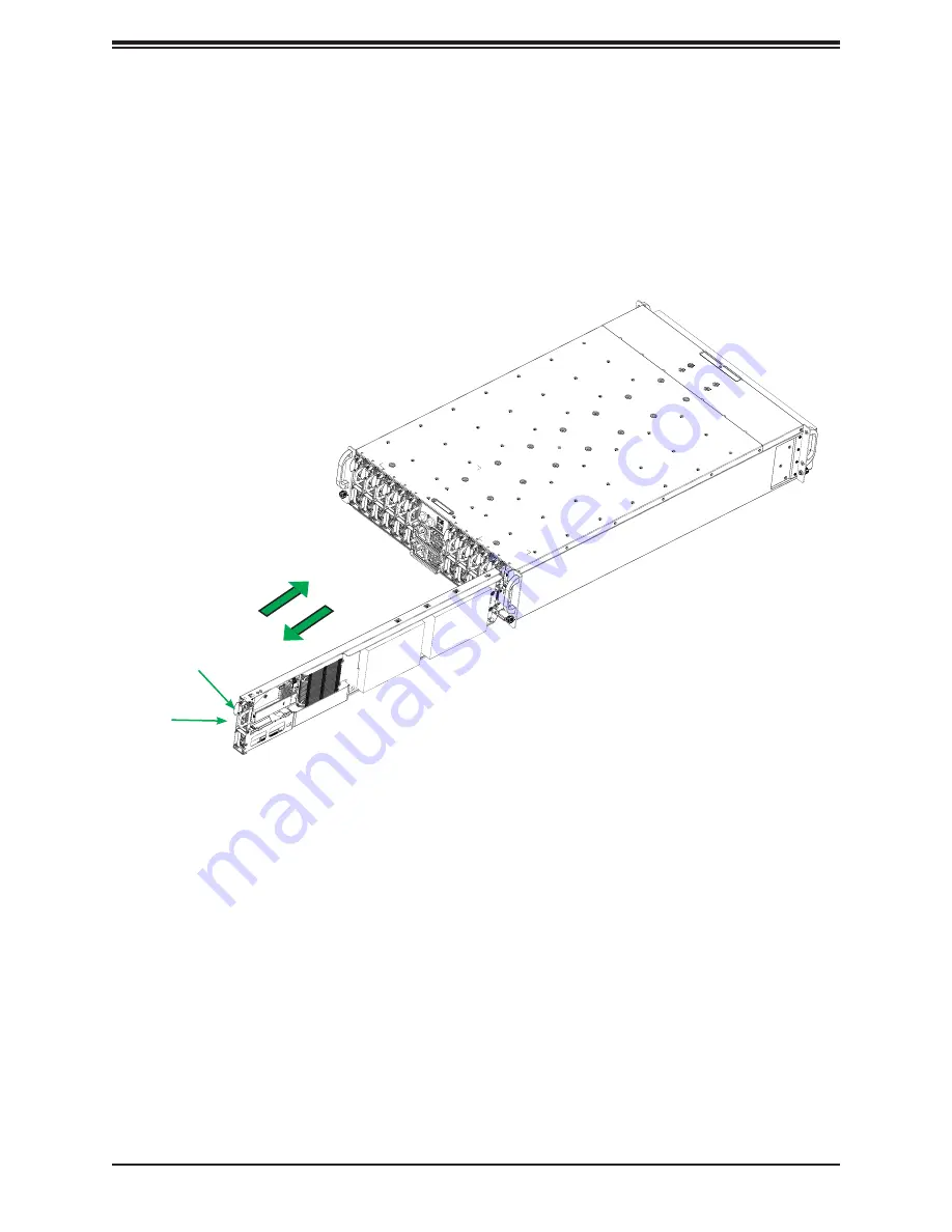
Removing and Installing Nodes

The system features twelve removable nodes. Each node contains an individual motherboard 
and hard drives mounted on a sled, which allows it to easily be installed and removed from 
the chassis.

Figure 3-2. Removing/Installing a Node

Removing a Node from the System

Note

: The system must remain locked in the rack while nodes are removed or installed.

1. Power-down the individual node by pressing that node power button.

2. Press and hold down the release tab on the front of the node.

3. Use the node handle to pull the node from the system.

Note:

 Do not operate the server with a node bay empty for long periods of time. If necessary, 

replace it with a dummy node that was included with the system accessory box.

Release Tab

Handle

Summary of Contents for SuperServer 530MT-H12TRF

Page 1: ...USER S MANUAL Revision 1 0a SuperServer 530MT H12TRF...

Page 2: ...ass A device or in residential environment for Class B device This equipment generates uses and can radiate radio frequency energy and if not installed and used in accordance with the manufacturer s i...

Page 3: ...rs and utilities https www supermicro com wdl Product safety info http www supermicro com about policies safety_information cfm If you have any questions please contact our support team at support sup...

Page 4: ...2 1 Overview 16 2 2 Unpacking the System 16 2 3 Preparing for Setup 16 Choosing a Setup Location 16 Rack Precautions 17 Server Precautions 17 Rack Mounting Considerations 17 Ambient Operating Temperat...

Page 5: ...Me Drive 32 M 2 SSD 33 3 7 System Cooling 34 Fans 34 Replacing Fans 35 Air Shroud Node 36 3 8 Power Supply 37 Power Supply LEDs 37 Changing the Power Supply 37 3 9 Expansion Module 39 Chapter 4 Mother...

Page 6: ...System Becomes Unstable 55 7 4 POST Codes 57 7 5 Crash Dump Using the BMC Dashboard 57 7 6 UEFI BIOS Recovery 58 Overview 58 Recovering the UEFI BIOS Image 58 Recovering the Main BIOS Block with a USB...

Page 7: ...Super Micro Computer B V Het Sterrenbeeld 28 5215 ML s Hertogenbosch The Netherlands Tel 31 0 73 6400390 Fax 31 0 73 6416525 Email sales supermicro nl General Information support supermicro nl Technic...

Page 8: ...5 or four fixed 2 5 drives two SATA NVMe and two SATA only One M 2 M key 2280 22110 PCIe x4 SATA One SuperDOM disk on modules connector Expansion Slots per node One PCIe 4 0 x8 Slot for AOM BPN MC12S...

Page 9: ...dules Service Asset Tag with BMC Password 11 2 12 10 9 8 7 6 5 3 4 1 BMC LANs Power Supply Indicator LEDs on the power supplies indicate the status of the module Power Supply Indicator LED Color and S...

Page 10: ...when power is on Asset Tag Service Asset tag with the BMC password KVM Port One VGA one COM and two USB 2 0 with KVM dongle USB Port USB 3 2 Type C Node LANs Two ports provided by the Supermicro Micro...

Page 11: ...11 Chapter 1 Introduction Rear View Figure 1 3 System Rear View...

Page 12: ...atsink Intel Xeon E 2300 Family and Pentium series processor with heatsink Network Card Supermicro Micro LP card providing LAN ports DIMM slots Four memory slots under and air shroud Storage Drives Tw...

Page 13: ...I E 4 0 X4 SATA 3 0 KEY M JBM1 JUSB3P1 USB 3 4 3 2 USB1 2 MH2 MH10 MH11 MH1 JPT1 JTPM1 JUSB1 USB2 3 0 JSD1 MH5 CPU MICRO LP PCIe 4 0 X8 JVRM1JPG1 JCPLD1 JPME2 JPO1 JWD1 X12STE F REV 1 00 DESIGNED IN U...

Page 14: ...tion BT1 Onboard Battery I SATA6 SATA 3 0 Port J2 MicroLP PCIe 4 0 x8 Slot for AOM BPN MC12SN J5 PCIe 4 0 x8 Slot J6 M 2 PCIe 4 0 x4 SATA 3 0 Key M 2280 22110 JKVM1 VGA COM1 USB Connector on the I O B...

Page 15: ...X SATA III DOM RTL8211FS Intel LGA1200 x8 DMI 5 0GT s 480Mbps USB2 7 11 5Gbps SVID Port 20 IMVP8 AST2600 FLASH SPI 16MB USB3 0 IMVP8 1 X USB A type USB2 5 1Gb s PCIe x8 MLP SLOT SMBUS 1000BASE X Port...

Page 16: ...be situated in a clean dust free area that is well ventilated Avoid areas where heat electrical noise and electromagnetic fields are generated It will also require a grounded AC power outlet nearby Be...

Page 17: ...y precautions in Appendix A Determine the placement of each component in the rack before you install the rails Install the heaviest server components at the bottom of the rack first and then work your...

Page 18: ...be maintained at all times To ensure this the rack itself should be grounded Particular attention should be given to power supply connections other than the direct connections to the branch circuit i...

Page 19: ...ping Release these screws just enough to allow the rails to slide apart Note the arrow on the rail which indicates the end that attaches to the front of the rack 2 Note that the rails are left right s...

Page 20: ...w on each side of the server to lock it into place Figure 2 3 Installing the System into the Rack Stability hazard The rack stabilizing mechanism must be in place or the rack must be bolted to the flo...

Page 21: ...given Installation or replacement of most components require that power first be removed from the system Please follow the procedures given in each section 3 1 Removing System Power Use the following...

Page 22: ...des can be accomplished while the system is in the rack Keep the system secure in the rack with the thumbscrews because there are no locking latches in the rail system Connecting to a Node USB COM and...

Page 23: ...ing a Node Removing a Node from the System Note The system must remain locked in the rack while nodes are removed or installed 1 Power down the individual node by pressing that node power button 2 Pre...

Page 24: ...otection When handling the processor package avoid placing direct pressure on the label area of the fan Check that the plastic protective cover is on the CPU socket and that none of the socket pins ar...

Page 25: ...f Pin 1 Holding the CPU by the edges with your thumb and index finger align the triangle on the CPU with the triangle on the socket The CPU keys the semi circle cutouts may also be aligned against the...

Page 26: ...26 Chapter 3 Maintenance and Component Installation CPU properly installed Load lever locked into place 5 Close the load plate then gently push down the load lever into its locking position...

Page 27: ...y tighten screws 1 2 then 3 4 to ensure even pressure The order of the screws is shown below To avoid damaging the processor or socket do not use a force greater than 12 lbf in when tightening 1 4 2 3...

Page 28: ...4 0 X4 SATA 3 0 KEY M JBM1 JUSB3P1 USB 3 4 3 2 USB1 2 MH2 MH10 MH11 MH1 JPT1 JTPM1 JUSB1 USB2 3 0 JSD1 MH5 CPU MICRO LP PCIe 4 0 X8 JVRM1JPG1 JCPLD1 JPME2 JPO1 JWD1 X12STE F REV 1 00 DESIGNED IN USA M...

Page 29: ...power from the system as described in Section 3 1 Follow the memory population sequence in the table above 1 Push the release tabs outwards on both ends of the DIMM slot to unlock it Notches Release T...

Page 30: ...the motherboard Replacing the Battery Begin by removing power from the system 1 Push aside the small clamp that covers the edge of the battery When the battery is released lift it out of the holder 2...

Page 31: ...mpatible storage drives see the X12STE F motherboard page Installing Hard Drives 1 Power down the node and remove it from the chassis following the procedure in Section 3 2 2 Insert the hard drive wit...

Page 32: ...the Temperature of an NVMe Drive There are two ways to check using the BMC Dashboard Checking a Drive BMC Dashboard Server Health NVMe SSD Shows the temperatures of all NVMe drives BMC Dashboard Serve...

Page 33: ...with plastic lock pin Standoff Hole for 2280 Installing an M 2 SSD 1 Ensure the plastic lock pin is inserted in the correct standoff hole for the form factor 2280 or 22110 of your M 2 card 2 Insert M...

Page 34: ...ntenance and Component Installation 3 7 System Cooling Fans Each three nodes each share a fan as described in the figure below Figure 3 13 Corresponding Nodes and Fans Fan 1 Fan 3 Fan 4 Fan 2 1 2 3 5...

Page 35: ...eplacing a Fan 1 Visually inspect the fans to see which one has failed 2 Push both release tabs on the fan inward 3 Pull the fan from the chassis The electrical connections disconnect automatically Wa...

Page 36: ...ow to maximize fan efficiency The air shroud does not require screws Installing the Air Shroud 1 Remove the node from the chassis onto a flat non conductive surface 2 Place the air shroud in the chass...

Page 37: ...n When illuminated indicates that the power supply is on Blinking Green When blinking indicates that the power supply is plugged in and turned off by the system Blinking Amber When blinking indicates...

Page 38: ...38 Chapter 3 Maintenance and Component Installation Release Tab Handle Figure 3 16 Replacing a Power Supply Module Figure 3 17 Release Tab on Power Supply Module...

Page 39: ...Me U 2 PCIe x4 slots via the backplane The Micro LP expansion module is inserted into a riser card and secured to two brackets as shown below This assembly is inserted into the expansion slot on the m...

Page 40: ...m Module TPM which is available from Supermicro A TPM Port 80 connector is a security device that supports encryption and authentication in hard drives It allows the motherboard to deny access if the...

Page 41: ...four to 2 5 SATA BPN and one to 3 5 SATA BPN one SATA 3 0 with DOM power receptacle connector and one SATA 3 0 right angle receptacle connector SATA ports provide serial link signal connections which...

Page 42: ...ator can also be triggered using the BMC This button can also reset the BMC by holding longer See Chapter 7 BMC Reset for details Power Button Use this button to power on or off the node Settings can...

Page 43: ...2 1 Watchdog JWD1 controls the Watchdog function Watchdog is a monitor that can reboot the system when a software application hangs Jumping pins 1 2 will cause Watch Dog to reset the system if an appl...

Page 44: ...Jumper Settings Jumper Setting Definition Pins 1 2 Enabled Pins 2 3 Disabled Onboard TPM2 0 Enable Disable Use JPT1 to enable or disable support for the onboard TPM 2 0 module The default setting is E...

Page 45: ...ifier LED LED2 is located right next to the unit identifier switch on the back panel of the motherboard Refer to p 33 for details about the LED BMC Heartbeat LED LEDM1 is the BMC heartbeat LED When th...

Page 46: ...supermicro com support manuals Installing the OS 1 Create a method to access the MS Windows installation ISO file That might be a DVD perhaps using an external USB SATA DVD drive or a USB flash drive...

Page 47: ...iver browse the USB flash drive for the proper driver files For RAID choose the SATA sSATA RAID driver indicated then choose the storage drive on which you want to install it For non RAID choose the S...

Page 48: ...Another option is to go to the Supermicro website at http www supermicro com products Find the product page for your motherboard and Download the Latest Drivers and Utilities Insert the flash drive or...

Page 49: ...etwork Management Protocol SNMP SuperDoctor 5 comes in local and remote management versions and can be used with Nagios to maximize your system monitoring needs With SuperDoctor 5 Management Server SS...

Page 50: ...our website at www supermicro com en solutions management software bmc resources BMC ADMIN User Password For security each system is assigned a unique default BMC password for the ADMIN user This can...

Page 51: ...s installed for a selection of bays drives of any storage protocol type can be inserted SATA The default configuration supports up to twelve SATA drives SAS An add on controller card and cables can su...

Page 52: ...ion offers downloads manuals BIOS BMC drivers etc FAQs RMA warranty and other service extensions Direct Links for the 530MT H12TRF System Web SYS 530MT H12TRF specifications page X12DPU 6 motherboard...

Page 53: ...ecurity Center for recent security notices Supermicro Phone and Addresses Direct Links continued 7 2 BMC Interface The system supports a Baseboard Management Controller BMC interface It provides remot...

Page 54: ...n card problems No Power Make sure that the power connector is connected to the power supply Check that the motherboard battery still supplies 3VDC If it does not replace it Check that the system inpu...

Page 55: ...f necessary System cooling Check that all heatsink fans and system fans work properly Check the hardware monitoring settings in the BMC to make sure that the CPU and system temperatures are within the...

Page 56: ...estion from the chassis and test it in isolation Replace it if necessary Or swap in a new component for the suspect one Or install the possibly defective component into a known good system If the new...

Page 57: ...AMI updates please refer to http www ami com products 7 5 Crash Dump Using the BMC Dashboard In the event of a processor internal error IERR that crashes your system you may want to provide informati...

Page 58: ...ed When the system power is turned on the recovery block codes execute first Once this process is complete the main BIOS code will continue with system initialization and the remaining POST Power On S...

Page 59: ...e BIOS binary image into a USB flash device and rename it Super ROM for the BIOS recovery use Note 2 Before recovering the main BIOS image confirm that the Super ROM binary image file you download is...

Page 60: ...shown above displays use the arrow keys to select the item Proceed with flash update and press the Enter key You will see the BIOS recovery progress as shown in the screen below Note Do not interrupt...

Page 61: ...EFI Shell prompt appears type fs to change the device directory path Go to the directory that contains the BIOS package you extracted earlier from Step 6 Enter flash nsh BIOSname at the prompt to star...

Page 62: ...complete When you see the screen above unplug the AC power cable from the power supply clear CMOS and plug the AC power cable in the power supply again to power on the system 10 Press Del continuously...

Page 63: ...e system Notes Clearing CMOS will also clear all passwords Do not use the PW_ON connector to clear CMOS JBT1 contact pads 7 8 BMC Reset The BMC can be reset using the UID button Reset Press and hold t...

Page 64: ...boot block code 3 If you still cannot resolve the problem include the following information when contacting us for technical support System motherboard and chassis model numbers and PCB revision numb...

Page 65: ...lure due to the alteration misuse abuse or improper maintenance of products During the warranty period contact your distributor first for any product problems Vendor Support Filing System For issues r...

Page 66: ...Europe Address Super Micro Computer B V Het Sterrenbeeld 28 5215 ML s Hertogenbosch The Netherlands Tel 31 0 73 6400390 Fax 31 0 73 6416525 Email sales supermicro nl General Information support super...

Page 67: ...sistance Only certified technicians should attempt to install or configure components Read this appendix in its entirety before installing or configuring components in the Supermicro chassis These war...

Page 68: ...idere los riesgos de la corriente el ctrica y familiar cese con los procedimientos est ndar de prevenci n de accidentes Al final de cada advertencia encontrar el n mero que le ayudar a encontrar el te...

Page 69: ...ient u zich bewust te zijn van de bij een elektrische installatie betrokken risico s en dient u op de hoogte te zijn van de standaard procedures om ongelukken te voorkomen Gebruik de nummers aan het e...

Page 70: ...n Attention Avant de brancher le syst me sur la source d alimentation consulter les directives d installation Circuit Breaker Waarschuwing Raadpleeg de installatie instructies voordat u het systeem o...

Page 71: ...el edificio Aseg rese de que el dispositivo de protecci n no sea superior a 250 V 20 A Attention Pour ce qui est de la protection contre les courts circuits surtension ce produit d pend de l installat...

Page 72: ...a y del cable el ctrico quitado de los m dulos de fuente de alimentaci n antes de tener acceso el interior del chasis para instalar o para quitar componentes de sistema Attention Le syst me doit tre...

Page 73: ...nt u alle spanningsbronnen en alle stroomkabels aangesloten op de voeding en van de behuizing te verwijderen Equipment Installation Warning Only trained and qualified personnel should be allowed to in...

Page 74: ...lar reemplazar o utilizar este equipo Attention Il est vivement recommand de confier l installation le remplacement et la maintenance de ces quipements des personnels qualifi s et exp riment s Warning...

Page 75: ...a de estas reas mediante la utilizaci n de una herramienta especial cerradura con llave u otro medio de seguridad Attention Cet appareil doit tre install e dans des zones d acc s r serv s L acc s une...

Page 76: ...e ou quivalent recommand e par le fabricant Jeter les piles usag es conform ment aux instructions du fabricant Advertencia Existe peligro de explosi n si la bater a se reemplaza de manera incorrecta R...

Page 77: ...evolen wordt Gebruikte batterijen dienen overeenkomstig fabrieksvoorschriften afgevoerd te worden Redundant Power Supplies Warning This unit might have more than one power supply connection All connec...

Page 78: ...te maken Advertencia Puede que esta unidad tenga m s de una conexi n para fuentes de alimentaci n Para cortar por completo el suministro de energ a deben desconectarse todas las conexiones Attention C...

Page 79: ...encia Cuando el sistema est en funcionamiento el voltaje del plano trasero es peligroso Tenga cuidado cuando lo revise Attention Lorsque le syst me est en fonctionnement des tensions lectriques circul...

Page 80: ...con las normas de electricidad locales y nacionales Backplane Waarschuwing Een gevaarlijke spanning of energie is aanwezig op de backplane wanneer het systeem in gebruik is Voorzichtigheid is geboden...

Page 81: ...lektriciteitsvoorschriften Warnung Die Entsorgung dieses Produkts sollte gem allen Bestimmungen und Gesetzen des Landes erfolgen Warning Ultimate disposal of this product should be handled according t...

Page 82: ...age de ce produit sont g n ralement soumis des lois et ou directives de respect de l environnement Renseignez vous aupr s de l organisme comp tent Hot Swap Fan Warning Warning Hazardous moving parts K...

Page 83: ...nilladores y todos los objetos lejos de las aberturas del ventilador Attention Pieces mobiles dangereuses Se tenir a l ecart des lames du ventilateur Il est possible que les ventilateurs soient toujou...

Page 84: ...r CAS zertifizierten Kabeln mit UL CSA gekennzeichnet an Ger ten oder Produkten die nicht mit Supermicro gekennzeichnet sind AC AC UL CSA UL CSA Supermicro Supermicro UL CSA UL CSA Supermicro UL CSA U...

Page 85: ...code pour tous les autres appareils lectriques sauf les produits d sign s par Supermicro seulement AC AC UL CSA UL CSA Supermicro UL CSA UL CSA Supermicro Advertencia Cuando instale el producto utilic...

Page 86: ...itmethode deze moet altijd voldoen aan de lokale voorschriften en veiligheidsnormen inclusief de juiste kabeldikte en stekker Het gebruik van niet geschikte Kabels en of Adapters kan een storing of br...

Page 87: ...edicated BMC LAN One USB Type C 3 2 port with KVM adapter One VGA two USB 2 0 one COM port Motherboard X12STE F 13 086 x 4 606 332 3 mm x 116 99 mm Chassis CSE 939HN R2K20BP holding twelve hot swap co...

Page 88: ...4 3 BS EN 61000 4 4 BS EN 61000 4 5 BS EN 61000 4 6 BS EN 61000 4 8 BS EN 61000 4 11 Environment 2011 65 EU RoHS Directive EC 1907 2006 REACH 2012 19 EU WEEE Directive California Proposition 65 Produ...

Page 89: ...Power Supply PDB HDD M 2 PDB Add on Card 1 0 1 wt 0 01 wt 2 3 Restricted substances and its chemical symbols Equipment name Type designation Type Note 1 Exceeding 0 1 wt and exceeding 0 01 wt indicat...

Page 90: ...90 Appendix B System Specifications 100 127V 60 50Hz 12 11A x2 200 240V 60 50Hz 10 9 5A x2 150 3...

Reviews: