A-4
SCA818S Backplane
User’s Guide
2. Jumper Settings and Pin Defi nitions
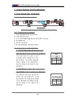
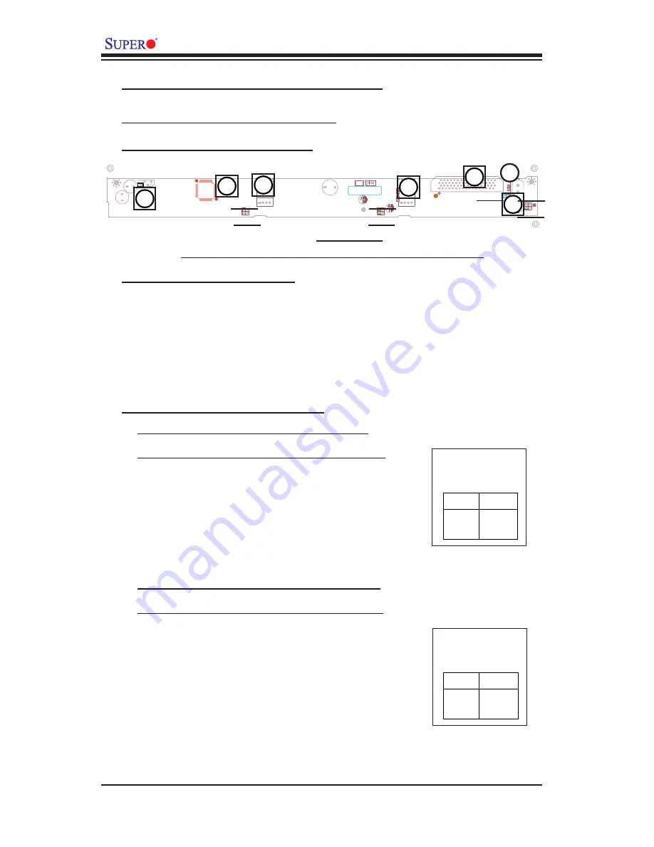
A. Front Jumpers and Connectors
Front Jumper/Connector Locations
(*See below for front connector/jumper descriptions.)
+
+
+
+
+12V
+5V
GND
+5V
+12V
GND
G
ND
+5V
+12V
GND
I C
2
+
+
+
+
SCA818S
UPER
S
R
Front View
B
A
C
JP21
E
D
JP18
A-2. Front Panel Connectors
A. JP10: Backplane Main (4-Pin) PWR
B. LVD1: SCSI Channel
C. J1, J2: CD-ROM/Floppy Drive (4-Pin) PWR Connector
D. 318 GEM Chip
E. JP9: I
2
C Connector
F. D4: Overheat/Drive Fail LED Indicator
C
JP19
JP22
JP23
JP20
JP17
A : SCA818S Backplane Main Power (J10)
Backplane Main Power Connector Pin Defi nitions
C: CD-ROM/Floppy Drive Power Connectors
CD-ROM/FDD Power Connector Pin Defi nitions
You must use the 4-pin power
connector (J10), marked "A" on the
layout above, to provide adequate
power supply to the Backplane.
See the table on the right for pin
defi nitions.
Pins #
1
2 & 3
4
Definition
+12 V
Ground
+5V
Backplane Main
PWR
4-pin Connector
(J10)
Pins #
1
2 & 3
4
Definition
+5 V
Ground
+12V
CD-ROM/FDD PWR
4-pin Connectors
Front Connectors and Pin Defi nitions
You must use the 4-pin power con-
nectors (J1, J2), marked "C" on the
layout above, to provide power supply
to the CD-ROM and Floppy Drives.
See the table on the right for pin
defi nitions.
F

