FatTwin F619P2/3-FT User's Manual
31
Drive Carrier Indicators
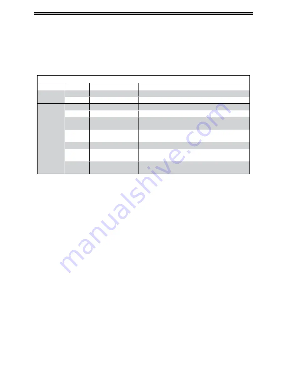
Each drive carrier has two LED indicators: an activity indicator and a status indicator. For RAID
configurations using a controller, the meaning of the status indicator is described in the table
below. For OS RAID or non-RAID configurations, some LED indications are not supported,
such as hot spare. For VROC configurations, refer to the VROC appendix in this manual.
Drive Carrier LED Indicators
Color
Blinking Pattern
Behavior for Device
Activity
LED
Blue
Solid On
SAS/NVMe drive installed
Blue
Blinking
I/O activity
Status
LED
Red
Solid On
Failure of drive with RSTe support
Red
Blinking at 1 Hz
Rebuilding drive with RSTe support
Red
Blinking with two blinks
and one stop at 1 Hz
Hot spare for drive with RSTe support
(not supported in VMD mode)
Red
On for five seconds,
then off
Power on for drive with RSTe support
Red
Blinking at 4 Hz
Identify drive with RSTe support
Green
Solid On
Safe to remove NVMe device
(not supported in VMD mode)
Amber
Blinking at 1 Hz
Attention state—do not remove NVMe device
(not supported in VMD mode)
Note:
Enterprise level hard disk drives are recommended for use in Supermicro chassis and
servers. For information on recommended HDDs, visit the Supermicro website at
supermicro.com/products/nfo/Ultra.cfm.
Hot-Swap for NVMe Drives
An NVMe drive can be inserted and replaced using IPMI.
Note
: If you are using VROC, see the VROC appendix in this manual instead.
Ejecting a Drive
1.
IPMI > Server Health > NVMe SSD
2. Select Device, Group and Slot, and click
Eject
.
After ejecting, the drive Status LED
indicator turns green.
3. Remove the drive.
Note that
Device
and
Group
are categorized by the CPLD design architecture.
Slot
is the slot number on which the NVMe drives are mounted.


