


35
Chapter 3: Motherboard Connections
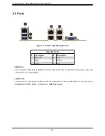
Universal Serial Bus (USB) Ports
There are two USB 3.0 ports (USB6/7) on the I/O back panel. The motherboard also has six
USB 2.0 headers (USB0/1, USB2/3, and USB4/5). To provide a USB connection at the front
of the system, connect a cable to one of the USB 2.0 headers. The cable is not included.
Front Panel USB 2.0
Header Pin Definitions
Pin#
Definition
Pin#
Definition
1
+5V
2
+5V
3
USB_PN2
4
USB_PN3
5
USB_PP2
6
USB_PP3
7
Ground
8
Ground
9
Key
10
Ground
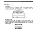
Unit Identifier Switch/UID LED Indicator
A Unit Identifier (UID) switch and an LED indicator are located on the motherboard. The UID
switch is located next to the VGA port on the back panel. The UID LED is located at LED1,
next to the UID switch. When you press the UID switch, the UID LED will be turned on.
Press the UID switch again to turn off the LED indicator. The LED indicator provides easy
identification of a system unit that may be in need of service.
Note:
UID can also be triggered via IPMI on the motherboard. For more information
on IPMI, please refer to the IPMI User's Guide posted on our website at
supermicro.com/support/manuals/
.
UID Switch
Pin Definitions
Pin#
Definition
1
Ground
2
Ground
3
Button In
4
Button In
UID LED
Pin Definitions
Color
Status
Blue: On
Unit Identified


