CM208W-TB Installation Guide
The CM208W-TB variant is designed to be installed in 2’ x 2‘ tile bridge ceilings.
You will need 18.5”
(47cm) of clearance above the tile grid for installation.
- The (4) eyebolts are included in the installation ring’s box. These should be installed first.
- At this point the installation ring can be flown into position (without the subwoofer attached).
It is never
recommended that the subwoofer be placed in the grid with no additional rigging to the supporting
structure.
Position the ring so that the bottom surface facing the floor is about 2.5” (64mm) from the flat
side of the tile grid (the surface where the grill will rest on). This will later need to be lowered about 1.5”
(38mm). It is highly recommended that turn-buckles be used in the rigging for this purpose and also to
make fine adjustments to the force exerted on the grill by the weight of the subwoofer to prevent the grill
from rattling. A bridle may be used so that only two attachment point are needed to the structure. At this
time it is also a good idea to confirm that the grid is well supported by hanger wire all around the subwoofer
location. At a minimum, all four corners of the grid opening selected should have a hanger wire less then 5
inches away.
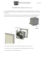
- Once the installation ring is in place, lift the subwoofer up through the 2’ x 2’ tile grid opening and the
installation ring. Make sure that the cut-aways on the subwoofer cabinet and the installation ring are
aligned. Push the subwoofer sideways to engage the installation ring in-between the bottom flange of the
subwoofer and the support piece (see below). A 2nd person can be used to hold the installation ring in place
while this is done. Push the subwoofer up into position using the support piece as leverage and fasten to the
installation ring with the (6) provided screws. The subwoofer should now be flown above the grid.
- Position the ladder underneath a grid opening next to the subwoofer. Take the grill up and slide it under-
neath the flown sub into the grid opening below. You should have about 1/4” clearance to do so.
- Using the turnbuckles or by loosening your rigging, lower the subwoofer approximately 1.5” (38mm) until
the rubber feet on the bottom of the cabinet just come into contact with the grill.
Support piece
Included fasteners
Matched Cut-aways
Included eyebolts
Page 8 of 11

