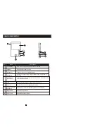
Super Circuits VIID1 User Manual Download Page 8

SPECIFICATIONS

Display

Resolution


 4 inch TFT LCD 


   320 (RGB) x 234

Conversation duration

Standby status    

Power supply

Operation temp. 

Installation 

Intercom mode

Working  status


Surface mount


400mA max

120 seconds


NOTE:

Do not 

install the device near strong radiation


sources, such as a 

TV set, video recorder

,


PC etc.          

Avoid shak

ing

beating

 on, or 

col

iding with the device. O

herwise

,

 internal components maybe 

damaged.

Do not apply power to the device until after it is completely i

nstall

ed

.

Position the AC 

power supply 

at least 12 inches away from the unit 

to avoid interference.  

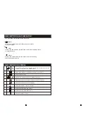
INSTALLATION OF INDOOR UNITS

Place the moni

Keep the unit 

away from the water and magnetic field.

Maintenance should be

 p

erformed by 

 a qualified technician. 

Install the monitor in 

the most suitable 

l

ocation, and at 

eye level. 

Plastic anchors

Bracket

Connection

cable

150-160c

m

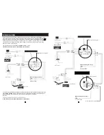
To install the indoor unit,


please 

f

ollow the diagram 

below:

Video system


PAL/NTSC compatible

CN5

Video

GND

External camera

Press the button to 


activate the function

End 

Real time 

surveillance 

Requirements:
1.


Connect the external camera

2.


In the standby  mode


Display 

the outside image


Press the button 
again to switch off
 

Note

In  monitoring  mode

if  a  visitor  press

es

  the  call  button 

 on e

ither 

outdoor unit,


the internal communication mode will be swithed off.

 Just the 


i

mage  will appear  on 

the

 screen  and 

continuous ringing

 will be played. 

You c

an  press  the 

T

alk 

button 

to reactivate  conversation  with the vis itor.

F or more  detailed  oprations,


please 

 see VISITOR CALL

on page  8.   

Surveillance  

MODE


50mA max.

    Duplex communication

Semi-


DC12V/1A

14 ~ 140 

°F (

-10 ~ +60 

°

C)

13

14


6.7 x 4.7 x .78 inches          


Dimensions

Summary of Contents for VIID1

Page 1: ...Indoor Monitor OPERATION INSTRUCTION 4 Wire Villa Video Intercom System User Manual...

Page 2: ...not prone to vibration or impact o o o o Use the appliance at temperatures between 10 C 60 C 14 F 140 F without excessive exposure to the extreme values indicated Install the devices away from heat s...

Page 3: ...image from the standby mode Talk Transmit the voice to outdoor camera Unlock Unlock the door lock by pressing this button Adjust the chroma contrast and luminace of TFT display Talk Volume Adjust the...

Page 4: ...ce of the TFT display Increase decrease the ring volume When lit this LED indicates this indoor unit is connected to main power supply When lit this LED indicates that this indoor unit is communicatin...

Page 5: ...n in the picture below and sockets Upto 4 indoor monitors canbe connected with 2 outdoor cameras A Red Audio B Yellow GND C Black Data D White Video J C N1 C N 2 C N3 C N4 1 R ed 2 Yel 3 B lk 4 Wh DC...

Page 6: ...et marked CN1 is for outdoor camera 1 and CN2 is for outdoor camera 2 Connect other extension monitors in in serial one by one The auxiliary connection of last extension monitor near the main monitor...

Page 7: ...from the indoor unit or which monitoring button was pressed last When you are transferring a call to other extension the original conversation indoor unit will return to standby mode and the indoor u...

Page 8: ...ian Install the monitor in the most suitable location and at eye level Plastic anchors Bracket Connection cable 150 160cm Toinstall the indoor unit please follow the diagram below Video system PAL NTS...

Reviews: