

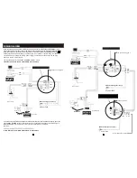


WIRING DIAGRAM
If you are using only
one outdoor camera, you must connect it to the socket marked
C
N1.
If the
only outdoor camera is connected
to the
CN2 socket
, the indoor unit will display a blank screen
when you attempt to activate
monitoring mode to 1st outdoor camera by pressing the button .
Please note that the part marked by the broken line is not present if you are using the indoor
unit, which has an internal switching power supply. Therefore you can connect the AC plug
directly to the AC power supply.
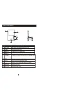
T he functionality of terminals C
N1 and CN2
is shown below:
1.Red:DC12V 2.Yellow: Audio 3.Black: GND 4.White:Video
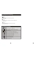
If you are using two outdoor cameras (for example, at the front door and the back gate), you must
use the
CN1
CN2
. The two wires for connecting to the outdoor units are shown in
the picture below.
and
sockets
Up to 4 indoor monitors can be connected with 2 outdoor
cameras.
A. Red: Audio B. Yellow: GND C. Black: Data D. White: Video
J
C N 1
C
N
2
C N3
C N4
1. R ed
2. Yel.
3. B lk.
4. W h.
DC 12V
Audio
G ND
V ideo
Dry
conta ct
4 3 2 1
AC100V~240V
External switching power supply
aa
a
aa
2P
short pin plugged in
Video
GND
External camera
CN5
3
OUTDOOR
CAMERA 1
J
C N 1
C
N
2
C N3
C N4
1. R ed
2. Yel.
3. B lk.
4. W h.
DC 12V
Audio
G ND
V ideo
Dry
conta ct
4 3 2 1
AC100V~240V
External switching power supply
a
aa
2P short pin plugged in
Video
GND
External camera
CN5
3
OUTDOOR
CAMERA 2
DC12V
Audio
GND
Video
4 3 2 1
A. Red
B. Yel.
C. Blk.
D. Wh.
CN3
A. Red
B. Yel.
C. Blk.
J 4
C N1
(not included)
CN4
D. Wh.
A. Red
B. Yel.
C. Blk.
D. Wh.
C
N
2
External switching power supply
CN
5
2P short pin pulled
To next extention unit C 3
N
AC100v-240V
GND
Camera
DC12V
Vide o
Select one
C
N
2
DC12V
Audio
GND
Video
4 3 2 1
(not included)
GND
Camera
DC12V
Video
Select one
OUTDOOR
CAMERA 2
GND
GND
7
8
C
N
2
OUTDOOR
CAMERA 1