

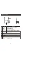


NOTE ON WIRING CONNECTION
OPERATION INTRODUCTION
VISITOR CALL
The Visitor press
the
call
button on
outdoor camera 1
A 10s of continuous
Ding
Dong tone is
played
inside and outside
The visitor
's
image
is
automatically displayed on
the screen
release the
door lock
Standby mode
Press the
unlock
button on indoor
monitor
Press the
T
alk
button
on indoor monitor again
End
The Visitor press
the
call
button on
outdoor camera 2
If
the
call button
s
o
f
two outdoor camera are pressed
at the same
time, the preference will be given to the outdoor camera
whose
call button was pressed first, unless the call button is pressed
again after the indoor monitor go
es
into standby mode
.
T
here is no indication on second outdoor camera
except that a
brief tone will
sound
on
the
indoor monitor.
NOTE:
Both the
sound
and image
from the camera remain on for
20
s
econds
after
the
unlock
button is pressed
.
Start conversation
with outdoor camera
Press the
T
alk
button
The indoor unit will automatically go into standby mode if you are
not
home or
d
o
not reach the indoor unit
with
in 60
s
econds
.
The conversation
duration is 120s
at a time
Stop ringing
NOTE:
Please be aware of Connection of 2 outdoor cameras is required.
Please
fol
l
ow the terminal
mark
ings
on PCB to avoid incorrect connect
ions
.
The wiring connection requirement :
1. 4C ordinary non-STP wiring cable,
Transmission
90 feet (0.2 mm = 24 AWG)
Wiring connection according to the following to avoid interference
Power+
Video
Audio
GND
GND
Audio
Power+
Video
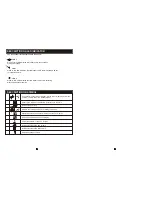
Both
Both outdoor units
must
be
connect
ed
to the main monitor
. T
he socket marked CN1
is for
outdoor camera 1
,
and
CN2 is
for
outdoor camera 2.
Connect
other extension
monitors in
in serial
,
one by one
. The
auxiliary connection of last extension monitor
(near
the
main monitor) is
connected
direct
ly
to main monitor
(the socket marked
CN4
).
Please note that the 2P
Short Pin
is designed for programming the indoor monitor
(see page
7 and
8
marked as )
. T
he indoor monitor will be programmed to main monitor if you plug
in
the
2P
Short Pin
; however the indoor monitor will be programmed to extension monitor if the
2P
Short Pin
is pulled out.
2. Effective distance from the outdoor camera to furthest
indoor monitor:
Transmission
160 feet (0.3 mm = 22 AWG)
Transmission
260 feet (0.4 mm = 20 AWG)
Normally,
the the system supports locks with Normally Open (N.O.) door unlocking
method.
This
means that in the normal state
,
the dry contact
s
(page5)
are
open so the lock
is in a
constant closed state.
Please
verify that connections of the external power source to the
power supply
are
correct
before applying power to the system. If connected incorrectly, severe
damage
can occur.
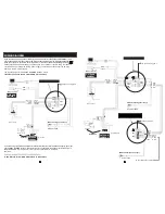
In addition
, the system
also supports connection
to
one external camera
. Y
ou
can also connect it
to o
ne external display. For
connection
details
(socket CN5)
, s
ee the diagram below:
Video
GND
CN5
External display
Video
GND
External camera
CN5
J3
Please note that the camera connected to CN2 is used to watch the image around the door if
the camera of outdoor unit
is masked. CN2 can be only connected one device, so you
can
select
either
outdoor unit 2
or the
camera.
Note that
the electric current
to
camera
is
300 mA max.
If the camera
in
outdoor unit is
masked, and can
't
see the image.
Press this button to watch the image
from camera. Press it again to back
to the image of outdoor
unit.
9
10