11
Be in charge.
Super B.
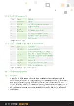
3.5.2. Con 2 (I/O connection 7)
PIN #
Range
Function
1
max 30 V dc
+ (Plus)
2
0-10 V dc
AN_SOC (Analogue state of charge)
3
NA
Nc (Not connected)
4
5A max
48V dc max
Rc, (Relay common contact)
5
Rnc, (Relay normaly close contact)
6
Rno, (Relay normaly open contact)
7
GND, (Ground)
Table 9. Con 2 (I/O connection 7)
3.5.3. Con 3 (CANopen; 5-pin “micro” style connector)
PIN #
Signal
Description
1
CAN_SHLD
Optional CAN Shield
2
CAN_V+
Optional CAN external positive supply
(dedicated for supply of transceiver and
optocouplers. if galvanic isolation of the bus
node applies)
3
CAN_GND
Ground / 0V
4
CAN_H
CAN_H bus line (dominant high)
5
CAN_L
CAN_L bus line ( dominant low)
Table 10. Con 3 (CANopen; 5-pin “micro” style connector)
3.6. Peripheral equipment
3.6.1. Obligatory
In order for the Li-ion battery to be used safely, an external disconnect device must be
installed. This should either be a relay or latching relay (bistable) controlled by the battery’s
BMS or a relay or latching relay controlled by a remote switch (CAN controlled). If an
external disconnect device is not installed the warranty of the Li-ion battery will be void. It
will lead to serious damage to the Li-ion battery and can lead to high risks for safety and
environment.


