background image

18

4.6.  Connecting the Li-ion battery to the load/charger

4.6.1.  Connecting a single Li-ion battery to the load/charger with a bistable relay

!

 Warning!

 Ensure you have completed all the previous steps described in chapter 4.5 before 

connecting the battery to the load/charger.

1.  Slide the terminal covers over the connection wires.
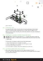
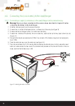
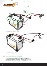
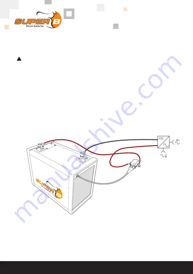
2.  Connect the + terminal of the battery to the - or B terminal of the relay (see figure 9).
3.  Connect the load or charger to the + or A terminal of the relay. 
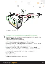
4.  Connect the - terminal of the battery. Do not connect the - terminal first as this may lead to short circuits 

(Figure 10).

5.  Ensure both contacts are tightened to 20 Nm. The contacts of the bistable relay must be tightened to 

max 13 Nm.

6.  Place the terminal covers over the terminals (see figure 10).
7.  Press the reset button for 10-15 seconds after connecting the bistable relay to Con1 output.(the reset 

button is located under the fuse cover). The bistable relay contacts will be turned off and on, this is to 
make sure that the bistable relay is ON

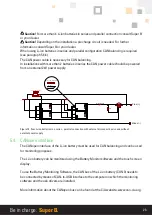
Load/Charger

Bistable Relay

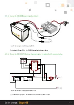
Figure 9.  Connecting the battery to the load

Summary of Contents for NOMIA 12V210AH

Page 1: ...Manual NOMIA 12V210Ah Version February 2021 ...

Page 2: ...the use of the product user safety should always be ensured so installers users service personnel and third parties can safely use the Li ion battery Copyright Super B All rights reserved Licensed software products are owned by Super B or its subsidiaries or suppliers and are protected by national copyright laws and international treaty provisions Super B products are covered by Dutch and foreign ...

Page 3: ... and battery controls 10 3 5 1 Con 1 Output for bistable relay 10 3 5 2 Con 2 I O connection 7 10 3 5 3 Con 3 CANopen 5 pin micro style connector 11 3 6 Peripheral equipment 11 3 6 1 Obligatory 11 3 6 2 Optional Components 12 4 Installation 13 4 1 General information 13 4 2 Unpacking 13 4 3 Preparing the battery for use 13 4 3 1 Placement of the battery 13 4 3 2 Placement and removal of a fuse 14 ...

Page 4: ...atteries in series and parallel 22 5 4 CANopen interface 23 5 4 1 CAN Bus network topology 24 5 4 2 Termination Resistors 24 5 4 3 CAN bus power 24 5 4 4 CAN balancing 25 6 Battery use 26 6 1 General information 26 6 2 Charging 26 6 2 1 Battery balancing 26 6 2 2 Reading out the battery s State of Charge SoC 26 6 3 Battery Monitoring Software 27 6 3 1 Battery History Recording 27 7 Inspection and ...

Page 5: ...nt manufacture capacity size or type Keep the Li ion battery clean and dry Secondary batteries need to be charged before use Always use the correct charger and refer this manual for proper charging instructions Do not leave the Li ion battery on prolonged charge when not in use After extended periods of storage it may be necessary to charge and discharge the Li ion battery several times to obtain ...

Page 6: ...y include off grid power supply marine power supply medium for renewable energy storage and traction battery for vehicles Use as a starter battery is not possible Up to 4 batteries can be connected in series or in parallel to increase the total capacity up to 840Ah For more batteries in series or parallel always consult with Super B 2 3 Glossary of Terminology BMS Battery Managent System Charge cy...

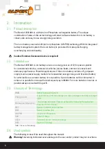
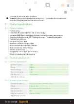
Page 7: ...Integrated fuse 32V 500A Maximum continuous discharge 500A Wired communication interface CANopen Battery monitoring History Storage Adaptive cell balancing Configurable in serial or parallel connection Output for bistable relay latching relay 3 2 Technical specifications 3 2 1 Electrical specifications Nominal capacity 210Ah Energy 2688Wh Nominal voltage 12 8V Open circuit voltage 13 2V Self disch...

Page 8: ...3 F Storage temperature long term 1 month 0 C to 35 C 32 F to 95 F Relative humidity 10 90 Table 5 Temperature specifications 2 Do not charge the Li ion battery below 0 C 32 F 3 2 5 Compliance specifications Certifications CE FCC UN 38 3 UN ECE R10 05 Shipping classification UN 3480 Table 6 Compliance specifications 3 2 6 General product specifications Battery designation IFpP 36 130 195 2P4S M 20...

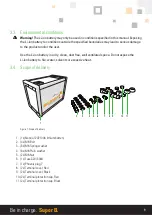
Page 9: ...he Li ion battery in a dry clean dust free well ventilated space Do not expose the Li ion battery to fire water solvents or excessive heat 3 4 Scope of delivery 2 3 4 5 6 7 8 10 11 9 1 Figure 1 Scope of delivery 1 1x Nomia 12V210Ah lithium battery 2 4x M8 Bolt 3 6x M8 Spring washer 4 6x M8 Plain washer 5 2x M8 Nut 6 1x Fuse 32V 500A 7 1x Phoenix plug 7 8 2x Terminal cover Red 9 2x Terminal cover B...

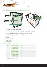
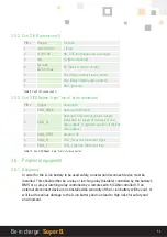
Page 10: ...ection 7 Phoenix FRONT MC 1 5 7 STF 3 81 1850903 3 Con 3 CANopen 5 pin micro style connector 4 Terminal 2x M8 5 Fuse cover 6 Terminal 2x M8 7 Reset button 8 Fuse connections 3 5 1 Con 1 Output for bistable relay PIN Output range 12V dc Function 1 2 7A continuous 15A 100ms pulse OFF 2 2 7A continuous 15A 100ms pulse ON 3 2 7A continuous 15A 100ms pulse OFF 4 2 7A continuous 15A 100ms pulse ON Table...

Page 11: ...couplers if galvanic isolation of the bus node applies 3 CAN_GND Ground 0V 4 CAN_H CAN_H bus line dominant high 5 CAN_L CAN_L bus line dominant low Table 10 Con 3 CANopen 5 pin micro style connector 3 6 Peripheral equipment 3 6 1 Obligatory In order for the Li ion battery to be used safely an external disconnect device must be installed This should either be a relay or latching relay bistable cont...

Page 12: ...ale female Cable 10m SB CAN Male female Cable 10m 8718531360754 T splitter SB CAN T splitter 8718531360761 Battery Interface Box SB BIB LV48V350A 8718531360914 Battery Interface Box SB BIB LV48V600A 8718531360921 USB to CAN CAN Compact to USB 8718531361201 Battery monitor SB Monitor Software Mounting bracket ZC casing SB Battery Bracket for Nomia 12V100Ah 12V210Ah and 12V210Ah 8718531360693 Batter...

Page 13: ...tery beyond published maximum specifications Caution Charging at deep discharge conditions can lead to venting excessive heat or thermal runaway of the cells Caution This Li ion battery stores fault conditions internally like excessive charge current or deep discharge situations Super B uses this information in the warranty process Warning Do not overcharge the Li ion battery 4 3 1 Placement of th...

Page 14: ...re from the pole of the Li ion battery see paragraph 4 5 for the details 2 Disconnect the positive wire from the pole of the Li ion battery 3 Unscrew the fuse cover using the TORX key 4 Unscrew the fuse contacts using a 13mm wrench Warning Short circuit danger Avoid making a short circuit with the wrench 5 Place the new fuse between the contacts place washers and spring washers and tighten the fus...

Page 15: ...Never use the Li ion battery without a properly installed external disconnect device relay or bistable relay Protecting the Li ion battery is possible by one of the following ways 1 Connect a bistable relay to the Li ion battery s Con1 output 2 Connect a normal relay to the Li ion battery s Con2 I O connection 7 output 3 By using the SB BIB Battery Interface Box 4 By using the SB BCI C1 Battery Co...

Page 16: ...sconnect device 4 5 2 Connecting a normal relay as an external disconnect device 1 When using a normal relay connect it to Con 2 I O Connection 7 Pin 4 Rc and Pin 5 Rnc as displayed in figure 6 Normal relay Load Charger Figure 6 Connect a normal relay as an external disconnect device ...

Page 17: ...tle Sheet 15 03 2018 14 00 24V1P_BCI 1 1 FUSE S1 S2 FUSE J1 J2 J3 J4 S3 X1 X2 BT11 X1 X2 BT12 X1 X2 K2 22Ω 50W Minus 0 1 2014 DEC 09 R Pot Plus Manual Control 5A 5A BCI 1 RECOVER RELAY COM 2 RECOVER RELAY NO 3 RESET IN 4 RESET IN 5 PRECHARGE IN 6 PRECHARGE IN 7 OFF IN 8 OFF IN 9 ON IN 10 ON IN 10 LOAD 9 BATTERY 8 MAIN RELAY HIGH SIDE COM 7 MAIN RELAY HIGH SIDE NO 6 MAIN RELAY LOW SIDE COM 5 MAIN R...

Page 18: ...to the or A terminal of the relay 4 Connect the terminal of the battery Do not connect the terminal first as this may lead to short circuits Figure 10 5 Ensure both contacts are tightened to 20 Nm The contacts of the bistable relay must be tightened to max 13 Nm 6 Place the terminal covers over the terminals see figure 10 7 Press the reset button for 10 15 seconds after connecting the bistable rel...

Page 19: ...f the battery to the terminal of the relay GIGAVac GX14 GX16 series Connect the terminal of the battery to the A2 terminal of the relay 3 Connect the load charger to the terminal of the relay TE EV250 Connect the load or charger to the A terminal of the relay GIGAVac GX14 GX16 series Connect the load or charger to the A1 terminal of the relay 4 Connect the terminal of the battery Do not connect th...

Page 20: ...d Charger Figure 12 Securing the terminal covers 4 7 Disconnecting the Li ion battery 1 Turn off any device or charger the Li ion battery is connected to 2 Disconnect the negative wire from the terminal of the Li ion battery 3 Disconnect the positive wire from the terminal of the Li ion battery ...

Page 21: ...op 24V_2s1p sch Sheet 1 1 J2_IO J3_CAN J1_BREL J2_IO J3_CAN J1_BREL 0 1 2 3 4 5 6 7 8 Version Date Name Title Sheet 15 03 201 24V_2s1p 1 1 CAN_Term_Female CAN_Term_Male X1 X2 X1 X2 Plus Minus K1 Rc Rnc Rno 1 2 3 4 5 6 7 gnd V soc nc FUSE FUSE CAN Red Black CAN Power Cable Minus 0 1 2014 OCT 06 R Pot Plus Rc Rnc Rnc Rc Rnc Rnc Con J2 IO connections Rc pin 4 Rnc pin 5 5A Main Switch _ _ Fuse _ _ Fus...

Page 22: ...4 Three Li ion batteries in parallel with external disconnect device OK Equally divided battery current All batteries contribute equally to the current into the load NOT OK Current not equally divided Batteries closest to load will have the highest contribution to the current into the load Whereas batteries further away from load will have lesser current contribution Wear and tear will be higher o...

Page 23: ...Shee 15 0 24V_2s2p CAN_Term_Female CAN_Term_Male FUSE CAN Red Black CAN Power Cable X1 X2 X1 X2 X1 X2 X1 X2 Plus Minus K2 Rc Rnc Rno 1 2 3 4 5 6 7 gnd V soc nc FUSE 0 1 2014 OCT 06 R Pot Minus Plus Rc Rnc Rnc Rc Rnc Rnc Rc Rnc Rnc Rc Rnc Rnc Con J2 IO connections Rc pin 4 Rnc pin 5 5A Main Switch _ _ Fuse _ _ Fuse _ _ Fuse _ _ Fuse A1 A2 Figure 15 Four Li ion batteries in a series parallel connect...

Page 24: ... to CAN interface may be connected anywhere to the CAN bus Use termination resistors at the end nodes to prevent reflections on the line The value of this resistor should be 120 ohms 5 4 3 CAN bus power Due to the galvanic isolation between the BMS and the Li ion battery s CAN interface an external power supply is needed on the CAN bus The CAN bus can be powered through Con 2 I O Connection 7 or t...

Page 25: ... 3 4 5 6 7 gnd V soc nc FUSE FUSE CAN Red Black CAN Power Cable Minus 0 1 2014 OCT 06 R Pot Plus Rc Rnc Rnc Rc Rnc Rnc Con J2 IO connections Rc pin 4 Rnc pin 5 5A Main Switch _ _ Fuse _ _ Fuse A1 A2 Figure 17 Use of CAN power cable to power the CAN bus 5 4 4 CAN balancing When the Li ion battery is connected in a series configuration CAN balancing is required CAN balancing makes sure that all batt...

Page 26: ...harge drops below 20 to preserve the lifespan of the Li ion battery 6 2 1 Battery balancing During the batteries lifespan the cells within the Li ion battery may be unbalanced due to high discharge currents and short float charge periods This may result in a loss of capacity and unbalanced cells Cells may be balanced by means of the following procedure Apply a constant voltage of 14 4V and a curre...

Page 27: ...h sensors within the Li ion battery It also enables one to download a complete recording of the Li ion battery s properties over time The Battery Monitoring software and the hardware are not included with the Li ion battery An overview of these products is given in paragraph 3 6 2 6 3 1 Battery History Recording The battery history can be downloaded with the Battery Monitor software This recording...

Page 28: ...d Do not attempt to charge or use a damaged Li ion battery Do not touch the liquid from a ruptured Li ion battery 2 Observe and note the run time that a new fully charged Li ion battery provides for powering your product Use this new Li ion battery run time as a basis to compare run times for older batteries The run time of the Li ion battery will vary depending on the products configuration and t...

Page 29: ...rs over the Li ion battery s terminals during storage 5 Charge the Li ion battery to 80 of its capacity every year 9 Transportation Always check all applicable local national and international regulations before transporting a Lithium Iron Phosphate battery Transporting an end of life damaged or recalled Li ion battery may in certain cases be specifically limited or prohibited The transport of the...

Page 30: ...he procedures described in paragraph 4 3 2 The Li ion battery has been deeply discharged The BMS is now in fault condition Disconnect all loads and connect a charger to the Li ion battery Then press the reset button for at least 10 15 seconds to resolve the fault condition see paragraph 3 5 The Li ion battery has been overcharged The BMS is now in fault condition Disconnect the charger from the Li...

Page 31: ...ducts f installation of the Super B product by persons unskilled to work with electro technical devices or components g any other wrongful use contrary to the Super B s user manual or the safety instruction h any use contrary to the product specifications of that product i any acts of force majeure 12 4 The warranty period for parts of the product which have been repaired or replaced under the war...

Page 32: ...h consequential loss or c goodwill 12 8 To the extent that a court determines that the limitation of liability as meant in clause 12 7 cannot be invoked against a particular claim for damages by the customer Super B s liability for loss of property damage to property and bodily injury including death caused by the application of those particular Super B products shall in any event be limited to th...

Page 33: ...33 Be in charge Super B ...

Page 34: ...For more information please contact Super B Lithium Power B V Europalaan 202 7559 SC Hengelo Ov The Netherlands Tel 31 0 88 0076 000 E mail info super b com www www super b com Manual February 2021 ...

Reviews: