Sunways STH-10K-HT User Manual Download Page 21

40

41

6. General Operation

6.1 Display Operation

When the inverter is turned on, the following interfaces will be displayed on the OLED display, 
and you can check the information and modify the parameters of the inverter by short or long 
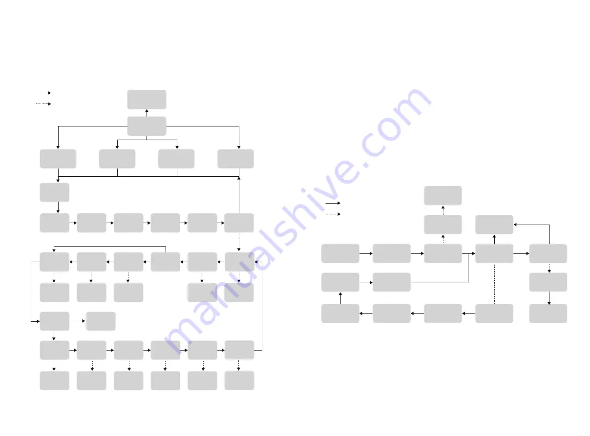
pressing the button. Please refer to the following display operation flow for details:

Tip: After every setting completed, wait for 10 seconds and the inverter will 

automaticaly save your settings or modifications.

Short press(1s),switch window

Long press(3s),enter the 

lower Menu

Firmware

Updating

PV Voltage

PV Current

Grid Voltage

Grid Current

Grid Frequent

Main Window

Waiting

Checking

E-DAY

Not WiFi

E-TOTAL

H-TOTAL

Model

Name

Safety Set

Safety Code

Export

Limit OFF

Export

Limit ON

WIFI

Reload

WIFI

Reset

Fault Info

RSSI

Setting

Feed in 

Grid XXX%

Setting

Power 

Factor

+/-X.XX

Setting

Grid 

Connect

Type Set

Four/Three

Wire System

Modbus 

Addr XXX

Setting

Time Set

Setting

Language 

Set

Setting

Setting

Setting

System 

Info

SN/FM 

Version

Error

Message

General

Settings

Normal Pac

Error Code

Return 

Main Window

6.2 Auto-Test

This function is disabled by default, and only will be functional in the safety code of Italy. 
Short press the button several times until “Auto Test CEI 0-21” displays on the screen, press 
and hold the button 3 seconds to activate “Auto Test”. After the auto test finished, short press 
the button several times until the screen displays “Auto Test Record”, and hold the button 3 
seconds to check the test result. 
The auto test type will be chosen from “Remote” and “Local” before starting the auto test. 
“Remote” is set as 1 by default, which only can be modified to “0” by sending an external 
command and “Local” is set as 0 by default, which can be modified to 1 through operating 
the button on the inverter.  According to the requirements of the standard, the test has been 
divided into three modes: 
1) “Remote” set as 1, “Local” set as 0, then the test order is 59.S1,59.S2,27.S1,81>.S2,81<.S2; 
2) “Remote” set as 1, “Local” set as 1, then the test order is 59.S1,59.S2,27.S1,81>.S1,81<.S1; 
3) “Remote” set as 0, “Local” set as 1, then the test order is 59.S1,59.S2,27.S1,81>.S2,81<.S2.
Connect the AC cable, auto test will start after the inverter connected to the grid, see the 
operation steps below:

6.3 Monitoring and Configuration

Sunways inverter provides a monitoring port that can collect data from the inverter and 
transmit it to Sunways monitoring website via an external monitoring data collector WiFi or 
LAN module. 

Please check the Sunways WiFi user manual for more details.

The auto test will start when the correct test item is selected, and the test result will be 
displayed on the screen when it finished. If the test success, it will display “Test Pass”, 
otherwise will display “Test Fail”. After each item tested, the inverter will reconnect to the grid 
and automatically start the next test item according to the requirements of CEI 0-21.

Remote Cmd

1

Select

Items

Wait

Wait

Wait

Wait

Wait

General 

Settings

Auto Test

CEI 0-21

Main Windows

IPS Item

xxxxx

Test Record

If 

Tested

Test Result

Display

Local Cmd

0

IPS Item

Test Null

Password

1111

Verify Ok

Password

1111

Setting

IPS Item

Test All

IPS Item 

Testing

Test Pass/Fail

Short press(1s),switch window

Long press(3s),enter the 

lower Menu

Summary of Contents for STH-10K-HT

Page 1: ...1 Three phase High voltage Hybrid Inverter STH 4K 5K 6K 8K 10K 12KTL HT User Manual Ningbo Sunways Technologies Co Ltd...

Page 2: ...e 16 3 4 Packing List 17 4 Product Installation 18 4 1 Selection of Installation Location 18 4 2 Mounting the Inverter 19 4 3 Electrical Connection 21 4 4 Communication Connection 34 4 5 Monitoring De...

Page 3: ...n and maintenance 2 1 6 To use this grid connected inverter for power generation needs the permission of the local power supply authority 2 1 7 During the operation of the inverter the surface tempera...

Page 4: ...e symbols displayed on the hybrid inverter nameplate and packing box 2 4 1 Symbols on the Hybrid Inverter Description Symbol Grid status indicator 2 4 2 Symbol on the Inverter nameplate The inverter c...

Page 5: ...d below STH 4KTL HT STH 5KTL HT STH 6KTL HT STH 8KTL HT STH 10KTL HT STH 12KTL HT 3 1 3 Applicable grid type The applicable grid types of the Sunways STH 4 12kW series are TN S TN C TN C S and TT When...

Page 6: ...in in if the battery is not enough Mode 2 In this working mode set the Pmax from grid in the App can realize the Peak Load Shifting When the loads consumption less than the Pmax loads are supplied by...

Page 7: ...ge the battery in the predetermined period Inverter will use power from PV and battery to supply loads in the predetermined period and the insufficient part will be supplied by the grid No Grid No Gri...

Page 8: ...ure 3 4 410mm 175mm Name Plate Logo Display 550mm 410mm Figure 3 5 Bottom view Figure 3 6 Inverter back view 3 2 3 Inverter bottom view as shown in Figure 3 5 3 2 4 Inverter back view as shown in Figu...

Page 9: ...the display Red An alarm or fault is detected view the fault info on the display 5 Display On Display the inverter operation information Off Display off to save power press the button to wake up the d...

Page 10: ...ectly to strong sunlight to prevent the power derating due to excessive temperature 4 The inverter should be installed in a place with shelter to prevent direct exposure to sunlight and rain 5 Install...

Page 11: ...ning 4 3 Electrical Connection Danger hint A high voltage in the conductive part of the inverter may cause an electric shock When performing any installation on the inverter make sure that the AC and...

Page 12: ...2 L1 CT C CT B CT A PV Strings Battery To Battery To Sunways Meter Power Meter Sunways Meter AC Breacker AC Breacker AC Breacker AC Breacker AC Breacker 1 phase Loads 3 phase Loads Loads FN Set Run Ac...

Page 13: ...stem all inverters PE wire need to be connected to the same grounding copper bar to ensure equipotential bonding 4 3 2 External ground connection Ground terminal connection steps 1 The external ground...

Page 14: ...o the corresponding positive and negative connectors pull back the cable to ensure that the terminal is tightly attached in the connector 6 Use an open end wrench to screw the nut to the end to ensure...

Page 15: ...ered when making AC output connection 1 An independent AC breaker is required in both inverter on grid and back up output side and any loads cannot be connected with inverter directly 2 Before making...

Page 16: ...ence as shown in Figure 4 23 Strip Length 8mm 40 60mm Wire Diameter 12 18mm Cables Screw cap The insulator AC sheet cover BACK UP ON GRID Single hole seal ring Figure 4 25 Figure 4 26 Figure 4 24 3 Pu...

Page 17: ...S1 10 L3 S2 12 L Power supplied from 220V grid 13 N RS485 RS485 Communicate with inverter CT installation direction and phase sequence should strictly follow the instruction in the user manual otherw...

Page 18: ...on bus interface EMS EMS power dispatching interface RLYOUT Dry contact output a group of normally open contact passive dry contact PARCAN EMS RLYOUT 4 4 2 Communication between inverter and meter The...

Page 19: ...ake sure the battery you selected is in the battery approval list of Sunways otherwise the system may not work properly Please contact your installer or Sunways service team for confirmation if you re...

Page 20: ...the installation represents that the assembly is in place 5 Start and Stop 5 1 Start Inverter When starting the inverter follow these steps 1 Turn the DC switch in the inverter bottom to the ON positi...

Page 21: ...te and Local before starting the auto test Remote is set as 1 by default which only can be modified to 0 by sending an external command and Local is set as 0 by default which can be modified to 1 thro...

Page 22: ...e installer or manufacture SPI Fault 1 Restart the inverter 2 Seek for help from the installer or manufacture E2 Fault 1 Restart the inverter 2 Seek for help from the installer or manufacture GFCI Dev...

Page 23: ...5 Voltage Harmonic Distortion 3 LinearLoad Model STH 4KTL HT STH 5KTL HT STH 6KTL HT STH 8KTL HT STH 10KTL HT STH 12KTL HT Efficiency Max Efficiency 98 1 98 1 98 1 98 2 98 2 98 2 European Efficiency 9...

Page 24: ...V1 01 EN Address No 1 Second Road Green Industrial Zone Chongshou Town Cixi City ZheJiang Province PEOPLE S REPUBLIC OF CHINA Website www sunways tech com Service Mail service sunways tech com Hotline...

Reviews: