Questions? Call or Text +1-801-658-0015 •
15
The Micro Welder Experts
settings and connections. Verify that the Weld On/Off
button is in the on state. If you need assistance, call the
Sunstone Customer Service team at +1 801-658-0015
or send a message to [email protected].
Weld Head Control Screen
Operation
The Weld Head Control Screen is used to set all param
-
eters required for controlling a connected weld head
during the weld process.
Note: The Weld Head Control Screen icon only appears
when a weld head is connected and powered on.
When you press the Weld Head Control Screen Icon
in the Navigation Bar, the Pico will begin a sequence
of step-by-step, pop-up windows to guide you
through the setup process.
You can choose to follow the step-by-step setup
process or jump to any portion of the setup process
by pressing any of the icons in the Weld Head Control
sub-navigation bar (found under the Navigation Bar
when the Weld Head Control icon is pressed). See Fig
-
ure 15.2.
MODE SELECT
The first step of the set up process is choosing
how you wish to control the weld head. The Mode Se
-
lect icon (A) in Figure. 15.2, is identical to the Weld Head
Control Screen icon due to it being an extension of
the weld head controls. The weld head has two modes
available: Direct Control and Automatic Control.
Direct Control
Direct Control allows operators to control the position
of the weld head directly by using an analog foot pedal.
The position of the weld head corresponds to the posi-
tion of the foot pedal. Pressing down on the foot pedal
lowers the weld head; letting up on the pedal raises the
weld head.
In this mode, the operator presses the analog foot
pedal to lower the weld head until contact is made with
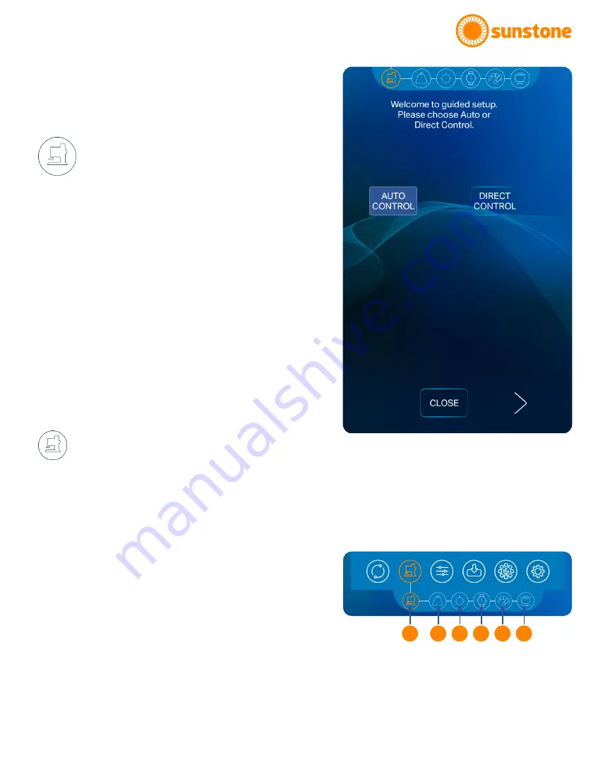
Figure 15.1. The Weld Head Control Screen in the Mode
Select step. When you touch the Weld Head Control Screen
icon, the Pico will want to walk you through a step-by-step
process to complete the weld head setup process. When
you’ve selected the desired settings for each step, press the
right arrow button at the bottom of the screen to advance to
the next step. You can press the left arrow button to go back.
Press the Close button to save and end the setup process.
A
B C D E F
Figure 15.2. The Weld Head Control Screen sub-navigation
bar contains six areas of weld head control: Mode Select
(A), Force (B), Position (C), Timing (D), Speed (E), and
Displacement (F).
Summary of Contents for PicoDC
Page 1: ...Direct Current Resistance Welder Users Guide 20210615 PART 1230 Pic...
Page 4: ...Users Guide Pic...
Page 41: ...Questions Call or Text 1 801 658 0015 37 The Micro Welder Experts...
Page 42: ...38 Questions Call or Text 1 801 658 0015 Users Guide Pic...
Page 43: ...Questions Call or Text 1 801 658 0015 39 The Micro Welder Experts...


