background image

7-47

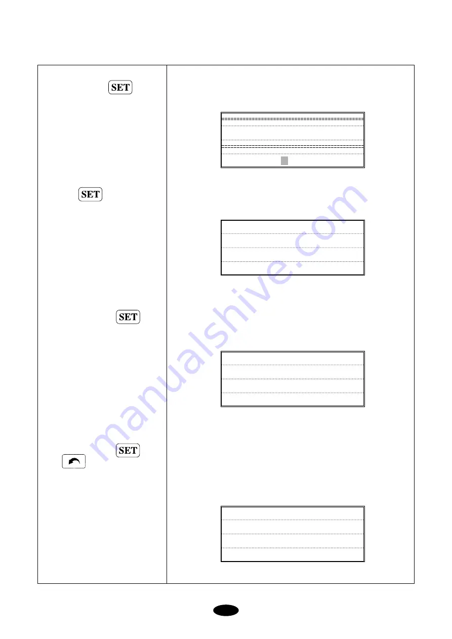
Place the cursor at 

2.DESIGN

DIVIDE

and press

DESIGN DIVIDE

STITCH=        [ST]

Input 1000 using the numerical keys

and press

SELECT EMPTY ROOM

===> # 18

To store sub-design 1, select #35

using the cursor. Press 

SELECT EMPTY ROOM

===> # 35

To store sub-design 2, select #36

using the cursor. Press 

Press                if you do not want to

store the sub designs

No.

:

5

NAME

:

SWF002

STITCH

:

18294

COLOR

:

7

Summary of Contents for D Series

Page 1: ...S SU UN NS ST TA AR R P PR RE EC CIIS SIIO ON N C CO O L LT TD D MANUAL FOUR HEAD AUTOMATIC EMBROIDERY MACHINE WITH FLAT SWF D Series SIX HEAD AUTOMATIC EMBROIDERY MACHINE WITH FLAT M MM ME E ...

Page 2: ...THIS IS AN INSTRUCTION FOR SAFE USE OF 4 6 HEAD FLAT AUTOMATIC EMBROIDERY MACHINES READ THOROUGHLY BEFORE USE ...

Page 3: ... 6 UPPER THREADING AND TENSION ADJUSTMENT 5 9 5 7 LOWER BOBBIN THREADING AND TENSION ADJUSTMENT 5 12 5 8 BOBBIN WINDER 5 13 5 9 FLOPPY DISKS 5 16 5 10 IN AND OUT OF DESIGNS 5 18 5 10 1 FLOPPY 5 18 5 10 2 TAPE 5 18 5 10 3 EMBROIDERY OUTPUT 5 18 5 11 RETURN TO PREVIOUS LOCATION IN UNEXPECTED BLACKOUTS 5 18 5 12 NEEDLE HOOK TIMING CONTROL 5 19 5 13 ASSEMBLY AND FUNCTIONS OF THREAD DETECTOR 5 24 5 13 ...

Page 4: ...NDARD VOLTAGE FOR X Y DRIVERS BY MACHINE TYPE 9 2 CHAPTER 10 MAINTENANCE AND INSPECTION 10 1 10 1 CHECK POINTS FOR REGULAR INSPECTION 10 1 10 2 CLEANING 10 1 10 3 OIL SUPPLY 10 3 10 4 DRIVE BELT TENSION 10 7 CHAPTER 11 MACHINE ADJUSTMENTS 11 1 11 1 ADJUSTING THE TRIMMERS 11 1 11 1 1 ADJUSTING THE POSITION OF THE TRIMMING CAM INSERT ANGLE OF MOVABLE BLADE 11 1 11 1 2 ADJUSTING SPACE BETWEEN MOVABLE...

Page 5: ...TION WARNING DANGER SAFETY RULES CHAPTER 1 ONLY TRAINED AND EXPERIENCED PERSONS FAMILIAR WITH THE RELEVANT SAFETY INSTRUCTIONS SHOULD HANDLE THE MACHINE MAKE SURE TO FULLY OBSERVE THE FOLLOWING INSTRUCTIONS 1 Using a crane Make sure that the crane is large enough to hold the machine Use a nylon rope of sufficient strength Place a wooden block at either side of the machine before tying the rope The...

Page 6: ...eight of the machine approximately 1 ton 2 Air conditioning can eliminate dust and humidity that can cause pollution and corrosion of the machine Make sure your machine is regularly cleaned 3 Long exposure to direct sunlight can cause the paint of the machine to fade or change of the machine shape 4 Allow at least 50cm 20 inches of space on each side of the machine for convenient maintenance Pleas...

Page 7: ...ear shoes with non slip soles 03 Clear all persons from the machine before turning on the power 04 Keep your hands or head away from the moving parts of the machine such as needle hook take up lever and pulley when the machine is in operation 05 Do not remove the safety cover on the pulley or shaft when the machine is in operation 06 Be sure the main power is turned off and the power switch is set...

Page 8: ...ry may be caused by moving needle Ensure that the machine is in a stop condition before changing threading or rethreading of needies or changing of needles Turn off the main power before rotating the main shaft by hand Do not remove covers during operation Turn off the main power before opening electricity related boxes WARING WARING WARING WARING Physical damage may be caused by interposition Whi...

Page 9: ...s or changing of needles ⓒ WARNING Fire or death may be caused by high voltage electric shock Don t open the cover except for service man assigned by SWF When open the cover turn off power and wait for 6 minutes Notice Cover in the WARNING means all covers near operating part of the machine Injury may be caused by winding Be sure to turn off the power before cleaning lubricating adjusting or repai...

Page 10: ...he right range of the voltage supply before installing or operating the machine The voltage required is as follows 1 Input voltage to be adjusted when installing 100V 110V 120V 200V 220V 240V 2 Allowed range of voltage within 10 of the voltage set 3 Electric capacity and voltage consumption 640VA 440W 4 Insulation resistance over 10M ohms measured with 500V insulation tester INSTALLATION AND MACHI...

Page 11: ...he machine will be installed Install the cable away from the operator s work space to prevent accident or injury If the difference in heights of the four bolts is over 10mm place spacers beneath the lower adjusting bolts to make the heights even 2 Use a nut to fasten the bolts when the machine is horizontally leveled CAUTION The level gauge does not measure accurately on a square pipe or a table F...

Page 12: ...Thread Stand Fig 2 4 Fig 2 5 Fig 2 6 2 Assembling Operation Box Spool plate Thread holder Operation box FDD Support CN6 I O Board to thread joint Board 40P CN2 From SPMS to joint PC Power input CN5 Joint Board to I O Board 34P CN5 Joint Board to I O Board 30P ...

Page 13: ...ge Upper thread holder Head Thread tension adjustment board Sub controller X axis driving system Y axis driving system Bar switch Frame Main controller box Operation box Encoder Main power switch Lamp Supporting bolt Leveling base Thread detector Emergency power switch Emergency stop switch PARTS OF THE MACHINE CHAPTER 3 ...

Page 14: ...C OFFSET at PARAMETER SELECT MODE to move the frame automatically to the desired point making it easier to do appliques and to switch the frames 7 MANUAL OFFSET You can manually move the frame to the pre selected point to do appliques or change the frames during embroidery work The frame can be moved back to its original place by simply pressing the right buttons 8 RETURN TO START The frame can be...

Page 15: ...nsert stitch data and function codes jump finish trimming 16 INDIVIDUAL HEAD OPERATION You can work on the specific head with a broken thread 17 MACHINE STOPPAGE The screen will indicate why the machine has stopped 18 RPM The screen indicates rpm 19 FRAME SPEED SET UP You can adjust the frame speed to high medium or low 20 UNUSED MEMORY The screen indicates the memory available for use 21 TAPE COD...

Page 16: ...key Indicator Lamp Indicates FIX POS Fixed Position which indicates the main shaft is not moving RUN MODE indicates that the machine is ready to accept and run the design Machine Information Button Selects machine information to be displayed on the screen See 7 2 MAIN INDICATION SCREEN for details Menu Button Selects the desired menu Fig 5 1 M SETTING FDD TRIM OFFSET PREVIOUS NEEDLE FLOAT FRAME ED...

Page 17: ...t during operation Press UP to increase and DOWN to decrease the speed ALL Button You can use this to input decimal numbers when setting the interval of repetition work It can also be used to work on the previous head after back stitching NOTE function Selects menu Sets number inputs Completes work when the machine stops during operation hold SET key until you hear a loud beep The machine will com...

Page 18: ... protects the floppy disk drive Disk Out takes the disk out FDD runs and reads the floppy disk Work Lamp blinks when FDD is in operation COM1 serial port 1 Parallel port COM2 serial port 2 Right Fig 5 2 Bottom Fig 5 3 ...

Page 19: ...h to Start the embroidery work or stop the machine during operation Move the frame back during machine stop Move forward in design during machine stop non stitching Move backward in design during machine stop non stitching Do work other than embroidery Bar switch STOP Left Right START Fig 5 4 NOTE Emergency power switch detects emergency stop failures and prevents accidents Emergency power functio...

Page 20: ...e selected movement units If you press START after the machine traveled 10 of the selected stitches the machine will continue to move forward Press START one more time and the machine will stop moving forward MACHINE OPERATION START STOP during machine stop BUTTON OPERATION Press STOP Hold STOP Press STOP again Frame moves backward in selected movement units see Note 2 Frame starts to move backwar...

Page 21: ...GENCY STOP if you have to stop the machine immediately i e machine error EMERGENCY STOP will turn off the machine To restart the machine rotate the main shaft to 100 Turn the EMERGENCY STOP button off and then on again Fig 5 7 Fig 5 6 ...

Page 22: ... may block smooth rotation of the roller and cause wrong detection of thread break CAUTION 1 The take up lever continues to operate even when the head is turned off This movement can cause the upper thread to come out of the holder Use a rubber magnet to fix the unused upper thread NOTE If you want to move the frame back for any reason when a thread break has NOT occurred press the toggle twice OF...

Page 23: ...Turn the clutch 90 in the direction of the arrow to stop the needle bar CAUTION The trimmer and the take up lever continue to move even when the needle bar is stopped by the clutch Avoid any operations i e threading the needle or changing thread Long time operation of the needle bar with the clutch may damage the bar controller ...

Page 24: ...ment board Thread detecting roller Thread detecting board Take up lever spring Rotary tension disk Main thread tension adjuster Upper thread guide Thread guide upper Take up lever Thread guide middle Thread guide lower Upper thread holder spring Presser foot Needle Fig 5 10 NOTE Do NOT stand on the table when threading the upper thread stand The table may be damaged ...

Page 25: ...Threading the sub tension adjuster Threading the main tension adjuster Threading the thread detector roller Threading around the needle Wrap the thread 1 5 times around the rotary tension disk V shaped groove Wrap the thread clockwise around the thread guide disk Wrap the thread around the detector roller one time Fix the upper thread between the thread holder spring of the lower thread guide Thre...

Page 26: ...ment ⓐ Tension on the take up spring affects the thread tension Turn the tension adjusting stud clockwise to increase the tension and counter clockwise to decrease the tension ⓑ Adjusting stroke of the take up spring To adjust the stroke of the spring during embroidery work move the take up spring stopper to right or left as shown in Fig 5 14 stopper Thread tension adjusting stud CORRECT WRONG Tak...

Page 27: ...use the thread to tangle during stitching 2 Lower Thread Tension Adjustment Adjust the tension of the lower thread using the nut on the tension spring on the bobbin case Turn the nut clockwise to increase the tension and counterclockwise to decrease the tension CAUTION 1 Direction of the Bobbin Rotation Make sure that the bobbin rotates clockwise when you pull the thread holding the bobbin case in...

Page 28: ...OX for changing fuse VOLTAGE SWITCH selects voltage supply CERAMIC ISLET hole for thread TENSION ADJUSTER NUT HOLDER NUT fixes thread holder stand BOBBIN PLATE ass y includes bobbin plate plate nut sponge bobbin holder bobbin shaft TENSION ADJUSTER adjusts thread tension on the bobbin THREAD HOLDER STAND THREAD HOLDER prevents tangles in thread from the bobbin Bobbin Stand unravels thread remains ...

Page 29: ...dial Set it at MAX to increase the volume Fig 5 19 Fig 5 18 Fig 5 20 4 Adjusting the Bobbin Wind Make sure to wind the thread parallel to the bobbin If not unfasten the screw on the thread guide body and adjust it left or right see Fig 5 19 Adjust the thread tension on the bobbin using a tension adjuster nut CAUTION 1 Winding the bobbin off center or uneven as shown below can cause thread breaks s...

Page 30: ...t start check and replace the fuse or switch If the bobbin shaft does not stop replace TR1 on the TIME switch or the circuit board If the winder does not start or stop replace the start stop switch or IC Wrong voltage may cause the machine to stop with a thud sound Replace Q1 on the circuit board MODEL NAME BW 02 Bobbin Winder 3 200rpm AC 110 220V 50 60Hz 10W 420 155 125 3 9kg 450 190 170 4 5kg SP...

Page 31: ... not remove the disk from the drive while formatting reading or writing the disk Do not open the cover of the disk drive Data cannot be written onto the write protected disks Repetitious reading and writing on a single disk may cause errors Save your important data on more than one disk for back up Fig 5 21 CAUTION You can use pre formatted disks but be sure to use disks of recognized quality Shut...

Page 32: ...Fig 5 22 Insert the floppy disk into the drive in the direction shown in the right picture of Fig 5 22 Taking out the Disk Press the Disk OUT button to take the disk out from the drive see Fig 5 22 CAUTION Do NOT remove a disk from the drive while formatting reading or writing the disk Otherwise the data may be lost ...

Page 33: ...to the memory using a tape reader provided as an optional kit see 7 24 Tape for details 5 10 3 Embroidery Output You can copy a design from the memory to the floppy disk see 7 21 Design Output 5 11 RETURN TO PREVIOUS LOCATION IN UNEXPECTED BLACKOUTS Your SWF machine goes back to the location of stop to pick up stitching when the power comes back on after unexpected blackouts See 3 4 4 Frame Moveme...

Page 34: ...change it If the needle is not clear of the plate manually turn the main shaft with a hand lever to put the needle in the right location for change CAUTION DB K5 needle has an eye twice larger than that of DB1 used for normal sewing Use DB X K5 for normal embroidery CAUTION Needle and thread most commonly used in embroidery are DB K5 11 and rayon yarn 120d 2 Fig 5 23 Needle Size Thread Size US 0 2...

Page 35: ...e bar CAUTION 1 For special threads such as artificial silk turn the needle slightly to the right to prevent thread breaks see Fig 5 25 CAUTION 2 If the needle is not inserted all the way to the top of the needle bar hole timing of the machine will go off causing broken needles and thread breaks Fig 5 24 Fig 5 25 Needle insert hole Needle groove front ...

Page 36: ...eedle the hook point will be inside the loop and threading will be more stable Fig 5 26 Fig 5 28 Hook point 0 1 0 3mm Fig 5 27 Top edge of needle eye Top point of hook circumference Needle tip c b a Top edge of the needle eye Hook allowance gap Hook point Lower dead stop of the needle Hook point a At lower dead stop of the needle bar 2 3 3 7 mm 1 8 2 2 mm 0 5 1 5 mm The figures may change accordin...

Page 37: ...Prevention of looping is important for stitching Adjust the hook point as close to the needle as possible to achieve the perfect thread position If thread breaks or stitches are unstable turn the needle slightly to the right NOTE Shape of the loop varies by the type of thread or fabric Unstable shape of the loop may result in skipped stitches The following pictures show different shapes of loop fo...

Page 38: ...ming Slow Hook Timing Fig 5 32 Too small Too large Fig 5 33 Fig 5 34 B C A Groove of the hook is in the A range The hook point will take up the thread when the loop is too small Stitching will be faster than the take up movement As a result the thread tension will be too loose upper thread loop will be too small and skipped stitches will occur Groove of the hook is in the B range The hook point wi...

Page 39: ...sembling Thread Detector You will need to disassemble the thread break detector unit to clean Remove the cover of the thread tension adjusting plate separate the cables and unfasten the roller base joint screw The entire unit will be disassembled including the rollers and bush bearing CAUTION Make sure to correctly place the thread detecting roller to have the unit properly function Check between ...

Page 40: ... WORK POSITION PUSH START SET UP FRAME OFFSET DO YOU WANT REPETITION DO YOU WANT AUXILIARY WORK GAUGE ETC DO YOU WANT FRAME OFFSET READ IN DESIGN READ IN THE SET UP IS THE OPERATIONG SYSTEM INSTALLED IS THE DESIGN INPUT KEY PRESSED ARE THERE PREVIOUSLY WORKED DESIGNS see 7 4 3 AUXILIARY YES YES NO INSTALL OPERATING SYSTEM TRACE READ DESIGN FROM DISK OR TAPE REPETITION ...

Page 41: ...EL CHAPTER 7 The first screen you will see when you turn on the main power looks like this After SWF EMB Vx xx is indicated on the screen the following information will be displayed there is no operating system in the memory and keys are pressed at the same time in the start screen SYSTEM VERSION YES CHECK IF KEYS WERE PRESSED DURING SYSTEM LOADING RUN OPERATING SYSTEM RUN SYSTEM INSTALLATION PROG...

Page 42: ... main shaft encoder 4 C C SETTING selects signals for the needle bar position 5 X ORIGIN SETTING checks origin on the X axis during machine inspection 6 Y ORIGIN SETTING checks origin on the Y axis during machine inspection 7 WIPER RET SENSOR checks wiper solenoid return sensor during machine inspection 8 START STOP CHECK checks START STOP buttons during machine inspection 9 SETTING DEFAULT turns ...

Page 43: ...into the drive and move the cursor to 1 VERSION INSTALL 1 VERSION INSTALL 2 VERSION BACKUP 3 ENCODER SETTING 4 C C SETTING 1 VERSION INSTALL 2 VERSION BACKUP 3 ENCODER SETTING 4 C C SETTING SYSTEM WRITE 55 SYSTEM READ 55 Press ...

Page 44: ...be at 12 MACHINE SETTING Press Press If you want to select WHEEL TYPE move the cursor to WHEEL If you want to select SPRING TYPE move the cursor to SPRING Move the cursor UP and DOWN to choose suitable WHEEL TYPE machine 12 MACHINE SETTING 13 EXIT 1 UK1204 2 UK1206 3 UK1202 4 UK1504 1 SWF T series 2 SWF W series 3 SWF U series SENSOR SETTING SPRING WHEEL WHEEL TYPE NORMAL 18HOLE 50HOLE ...

Page 45: ...the version as well S Y S T E M C H A N G E W E 1 2 0 6 X X X X X X X X Press Press 12 MACHINE SETTING 13 EXIT 12 MACHINE SETTING 13 EXIT Machine data display If you skip 12 MACHINE SETTING and go straight to 13 EXIT the machine will ask for your machine set up 12 MACHINE SETTING will automatically appear on the screen S W F W B V x x x SWF W 18R B Vx xx Wheel Normal Wheel 18 Hole SWF W 50R B Vx x...

Page 46: ...Machine SWF WE1206 SWF WF912 6 head Flat Embroidery Machine 12 head Flat Embroidery Machine SWF series T SWF UK1202 SWF UK1501 SWF UK1206 SWF UK1506 SWF UH1206 SWF UH1506 2 head Tubular Embroidery Machine SWF UK1204 SWF UK1504 4 head Tubular Embroidery Machine 6 head Tubular Embroidery Machine 6 head Compact Tubular Embroidery Machine SWF UH1208 SWF UH1508 8 head Tubular Embroidery Machine SWF UI1...

Page 47: ...nformation number of total stitches the stitches made and the progress percentage Work information current speed number of total stitches and number of total plates Needle bar information number of the previous current and next needle bars and the number of total colors D E S I G N 8 1 6 8 5 0 s t 0 1 6 8 5 0 s t 0 1200 S 115354 W 011 N 4 1 2 TOTAL 6 CAUTION The VFD also indicates cause of machine...

Page 48: ...elected design ANGLE the selected orientation of the design by degrees MIRROR if the reverse function is selected MIRROR if the reverse function is selected X_SCALE if the design has been scaled up or down in the X direction Y_SCALE if the design has been scaled up or down in the Y direction The above data are accurate based on instant calculation Sub Menus Main menus are selected by keys on the c...

Page 49: ...eed OPERATION mode moves the frame non stitching functions copying deletion formatting etc manual trimming set up offset set up the needle bar Basic Set Up Auxiliary Work Repetition Work Data Set Up Embroidery Design Edit Frame Movement Floating machine set up Machine Set Up Floppy Functions Manual Trimming Offset Set Up Needle Bar Set Up Previous Stop Start PP 7 4 1 PP 7 4 2 PP 7 4 3 PP 7 4 4 PP ...

Page 50: ...P SOL TEST WIPER SOL TEST PICKER SOL TEST TRIM SYSTEM TEST WHEEL SENSOR TEST DESIGN EDITING FRAME MOVEMENT NON STITCHING BASIC SET UP OFFSET SET UP GNT2910 GNT4604 SERIAL PARALLEL SERIAL PARALLEL FLOPPY PROCESS FDD SAVE FDD DELETE FDD FORMAT STITCH EDIT DESIGN DIVIDE DESIGN FILTERING SPEED CODE DATA ORIGIN ORIGIN POWER RESUME 100 STITCH 1000 STITCH 10000 STITCH COLOR X_SCALE Y_SCALE ANGLE MIRROR S...

Page 51: ... 1 EMB CALL Press size of the memory available will be displayed 1 EMB CALL calls the design from memory 2 FDD CALL reads design from the floppy disk 3 EXTERNAL INPUT reads design from an outside source 4 EXTERNAL OUTPUT outputs design from memory 5 DESIGN DELETE deletes design stored in memory 6 DESIGN COPY copies designs stored in memory 7 MEMORY INITIAL deletes all designs stored in memory 1 EM...

Page 52: ... design was called with no errors You can also check it through the Machine Information Screen 1 12372 2 5954 3 7281 4 17325 5 18294 6 13826 7 21064 8 16850 1 EMB CALL 2 FDD CALL 3 EXTERNAL INPUT 4 EXTERNAL OUTPUT No 8 NAME SWF STITCH 16850 COLOR 6 D E S I G N 8 1 6 8 5 0 s t ...

Page 53: ...WN keys or move to the GOLF design directly by using digit keys In such state you can confirm file name GOLF and design name SWF008 alternately as you use key 1 EMB CALL 2 FDD CALL 3 EXTERNAL INPUT 4 EXTERNAL OUTPUT 1 FILA 5720 st 2 PROWORLD 1377 st 3 CAF 646 st 4 P_WORLD1 7334 st MENUAL DISK SELECT EMB CALL DISK FREE STITCH 32300 STITCH 5 SANTA1 2540 st 6 BIRD1 7637 st 7 DUCK1 61703 st 8 GOLF 766...

Page 54: ...ETTE ZSK ZSKDISKETTE BARFMC BARUDANFMC BARFDR BARUDANFDR EXITorPREVIOUS END Design from room no 30 has been called Function that input automatically needle bar of ZSK diskette You can select information of needle bar in case of copy design of ZSK diskette When diskette constantly appears error you may select another diskette to press ZSK NEEDLE SEQ MANUAL 0 AUTO 1 MANUAL SELECT To save previous ne...

Page 55: ...Place the cursor at 2 NEEDLE SETTING and press to set up the needle bar Needle set up procedure is the same as pressing from the start menu Press to end the set up At Screen 1 you can press to start embroidery work or select 3 EMB CALL to re select design 1 BASIC SETTING 2 NEEDLE SETTING 3 EMB CALL 1 X_SCALE 100 2 Y_SCALE 100 3 ANGLE 0 4 MIRROR NO MIRROR NEEDLE SELECT 1 1 1 END INSERT DEL 1 BASIC ...

Page 56: ...910 and press Move the cursor to 25 Press 1 GNT2910 reads data from Tape Reader 2 GNT4604 reads data from Tape Reader 3 SERIAL enables data correspondence between PC and the machine 4 PARALLEL reads data from SWF NET1 1 GNT2910 2 GNT4604 3 SERIAL 4 PARALLEL SELECT EMPTY ROOM 15 PRESS SET TO START EXIT TO PREVIOUS NOW DATA READING ...

Page 57: ...chine via SERIAL communication Call the desired design and select 4 EXTERNAL OUTPUT When the receiving machine presses SET the data will be transmitted with the following screen DO YOU WANT TO SAVE YES NO EXTERNAL OUTPUT DATA PENDING EXTERNAL OUTPUT DATA SENDING The tape format is automatically detected as shown above Procedures for GNT4604 and SERIAL are the same as for GNT2910 1 SERIAL 2 PARALLE...

Page 58: ...s Move to 30 by moving the cursor UP DOWN or using the numerical keys Press to delete If there are more designs to delete repeat the process Press PREVIOUS 2 FDD CALL 3 EXTERNAL INPUT 4 EXTERNAL OUTPUT 5 DESIGN DELETE 1 992 2 5954 3 7281 4 17325 1 992 2 5954 3 7281 4 17325 No 2 NAME SWF001 STITCH 5954 COLOR 4 14 10898 15 55961 16 5718 30 7667 ...

Page 59: ...IGN COPY Press NOT LOAD DESIGN 3 EXTERNAL INPUT 4 EXTERNAL OUTPUT 5 DESIGN DELETE 6 DESIGN COPY 1 992 2 5954 3 7281 4 17325 2 5954 3 7281 4 17325 5 18294 Move to 5 by moving the cursor UP DOWN or using the numerical keys If you delete a design that is currently in use you will see the following message On Machine Information Screen On Menu Screen S W F E M B ...

Page 60: ...35 by moving the cursor UP DOWN or using the numerical keys SELECT EMPTY ROOM 17 SELECT EMPTY ROOM 35 Selecting the memory room 1 EMB CALL 2 FDD CALL 3 EXTERNAL INPUT 4 EXTERNAL OUTPUT No 2 STITCH 5954 COLOR 4 JUMP 0 Press Press ...

Page 61: ...cursor at 7 MEMORY INITIAL Move the cursor to YES to delete and press if you don t want to delete select NO and press SET 4 EXTERNAL OUTPUT 5 DESIGN DELETE 6 DESIGN COPY 7 MEMORY INITIAL 1 EMB CALL 2 FDD CALL 3 EXTERNAL INPUT 4 EXTERNAL OUTPUT NOT LOAD DESIGN DO YOU WANT TO FORMAT YES NO Press Press ...

Page 62: ...n along the X axis left to right The default is 100 and the allowed range runs from 50 to 200 The default is 100 and the allowed range runs from 50 to 200 Y_Scale Reduces or enlarges the design along the Y axis top to bottom 100 200 100 200 100 0 90 200 Designs can be enlarged in both the X and the Y directions The default is 0 and designs can be rotated from 0 to 359 Angle Rotates the design in a...

Page 63: ...axis No YES No No YES YES Mirror on the Y axis Mirror on the X Y axis START ST Selects the start location on the design You can skip certain number of stitches and start from the desired location Start Start End End Empty stitch 5 000 st Total stitch 10 000 st Start stitch 5 000 st ...

Page 64: ...the width of a satin stitch in the Y direction Ex Calling and editing the design in memory 5 X SCALE 150 START ST 100 stitches Y SCALE 120 X SATIN 3 ANGLE 45 Y SATIN 2 MIRROR Y Select the design in memory 5 see 7 4 1 In and Out of Designs No 5 NAME SWF002 STITCH 18294 COLOR 7 1 X_SCALE 100 2 Y_SCALE 100 3 ANGLE 0 4 MIRROR NO MIRROR Press NOTE Basic set ups are not stored for each design When a des...

Page 65: ...up the Y Scale and press Input 120 and press X_SCALE 100 RANGE 50 200 X_SCALE 100 RANGE 50 200 150 Y_SCALE 100 RANGE 50 200 1 X_SCALE 150 2 Y_SCALE 100 3 ANGLE 0 4 MIRROR NO MIRROR The X scale has been set up as 150 1 X_SCALE 150 2 Y_SCALE 120 3 ANGLE 0 4 MIRROR NO MIRROR The Y scale has been set up as 120 Press ...

Page 66: ...TART ST X SATIN and Y SATIN Move the cursor to check if all the settings have been input correctly ANGLE 0 RANGE 0 359 1 X_SCALE 150 2 Y_SCALE 120 3 ANGLE 45 4 MIRROR NO MIRROR 1 X_SCALE 150 2 Y_SCALE 120 3 ANGLE 45 4 MIRROR Y MIRROR 4 MIRROR Y MIRROR 5 START ST 100 st 6 X SATIN 3 7 Y SATIN 2 No 5 NAME SWF002 STITCH 18294 COLOR 7 Press ...

Page 67: ...MEASURE measures the length between two selected points 2 DESIGN TRACE checks the outline area of the selected design 3 OPTIMIZE TRACE traces the shape of the selected design JUMP 7 X mm 96 5 Y mm 135 0 ANGLE 45 The X and Y lengths changed and the Angle is set at 45 degrees Machine Information Screen shows 100 stitches progressed already 100 18294 st 0 1 LENGTH MEASURE 2 DESIGN TRACE 3 OPTIMIZE TR...

Page 68: ...MEAUSRE in the sub menu Press Use the frame move key to move to the desired point Press when you want to stop 1 LENGTH MEASURE 2 DESIGN TRACE 3 OPTIMIZE TRACE X 0 Y 0 MACHINE INFORMATION DISPLAY X 1 0 8 Y 8 5 Lengths in the X and Y directions up to the cursor are indicated on the screen in mm as you move the frame MENU DISPLAY LENGTH MEASURE ...

Page 69: ...how the path of the design trace The design will be traced at its furthest points maximum and minimum X and Y If the design is too large for the hoop the frame stops and the message Frame Limit Error will appear on the screen To use this function select and in the start menu to set the frame limits and set to YES in the EMB FUNCTION 15 Frame Limit 3 Frame Limit Set 2 Machine SET Machine Set Up Sta...

Page 70: ...ign Trace and press Press when the trace is finished No 5 NAME SWF002 STITCH 18294 COLOR 7 1 LENGTH MEASURE 2 DESIGN TRACE 3 OPTIMIZE TRACE Frame traces the design with this screen FRAME TRACE CAUTION If the frame hits the needle bar or any other part of the machine during tracing press immediately and then press ...

Page 71: ...ath of the trace The design will be traced at its furthest points If it is too large for the hoop the frame stops and the message Frame Limit Error will appear on the screen To use this function select and in the start menu to set the frame limits and set to YES in the EMB FUNCTION 15 Frame Limit 3 Frame Limit Set 2 Machine SET Machine Set Up Start ...

Page 72: ...ction Set the direction using buttons Moving 30mm Moving 30mm repetition from left to right repetition from right to left Start point of design Move Move Embroidery start point 30 mm 30 mm Y DESIGN INTERVAL Set the distance between the start points of the design in the Y direction Set the direction using buttons repetition from bottom to top repetition from top to bottom 1 X REPEAT sets the number...

Page 73: ...ops JUMP CODE design moves to the next location and automatically starts work NEEDLE BAR SET UP Needle bar set up should be different for STOP and JUMP CODES STOP CODE color change is automatically added at the start point of the design In the case of using four colors the following revision is made JUMP CODE color change is not added automatically so you are to select the exact number of colors u...

Page 74: ...X DESIGN INTERVAL 40mm DESIGN INTERVAL JUMP CODE Call the design from 5 see 7 4 1 In and Out of Designs Press Input 5 using the numerical key to set the number of X repetitions Press Input 5 using the numerical key to set the number of Y repetitions Press No 5 NAME SWF002 STITCH 18294 COLOR 7 REPEAT SETTING 1 X REPEAT 1 99 0 REPEAT SETTING 2 Y REPEAT 1 99 0 REPEAT SETTING 3 X Design Interval 300 3...

Page 75: ...sor to go to the next screen REPEAT SETTING 4 Y Design Interval 300 300 mm 0 REPEAT SETTING 4 Y Design Interval 300 300 mm 40 REPEAT SETTING 5 Y X Priority Y 0 X 1 Y REPEAT SETTING 6 Design Interval JUMP 0 STOP 1 JUMP You can check or change the set up data The data in the brackets is the set up data Input 40 for X design interval and press ...

Page 76: ...k Move the cursor to YES Press REPEAT SETTING 6 Design Interval JUMP 0 STOP 1 JUMP No 5 NAME SWF002 STITCH 18294 COLOR 7 JUMP 7 The screen shows that the repetition work is cancelled DO YOU WANT TO CANCEL YES NO DO YOU WANT TO CANCEL YES NO No 5 NAME REPEAT STITCH 457350 COLOR 182 ...

Page 77: ... Only the numerical key 0 works TOTAL WORK CLEAR Along with TOTAL WK in the main function menu this indicates the number of table sets from clear to present Only the numerical key 0 works JUMP CONVERT The machine trims if jump code is repeated more than the set up data You will need to set up the number of repeated jump stitches required for long stitch work The default is 3 stitches and the range...

Page 78: ...ncrements of 0 1 mm BK_ST UNIT This sets the number of stitches to be made at a single bar switch action when you do forward or backward stitching using the bar switch The default is 1 stitch and the range is 1 10 stitches in the increments of 1 stitch BK_ST START When you moved the frame back from the stopped position to work with a bar switch you can set whether the stitching will start automati...

Page 79: ...ms trimming and resumes work You can set the maximum jump stitch length for this process The default is 0mm and the range is 0 50mm in the increments of 1mm THE BRK MOVE When the machine stops after detecting a thread break the frame moves back automatically for convenient upper threading You can set the length of this frame move The default is 0cm and the range is 0 30cm in the increments of 1cm ...

Page 80: ...n off this function AUTO C C This selects the automatic color change function The default is YES and you can select NO to turn off this function MAX SPEED This sets the maximum machine speed The default varies by machine type in the following range You can set in the increments of 10 rpm Maximum speed limit Automatic color change Automatic trimming Length of thread tail after trimming series serie...

Page 81: ...s NO and you can input 1 to set it to YES POWER ORG This selects the frame to move back to the start position when the power comes on FRAME SPEED This sets the speed of the frame movement such as automatic return to start position or offset movement The default is LOW 0 and you can select HIGH 1 for high speed SPEED DATA This decreases the overall embroidery speed if the work material becomes too ...

Page 82: ...e following screen 1 0 0 J 2 0 0 J DEL INS EDIT 1 in the first line is a stitch number followed by X data Y data and JUMP CODE N normal CC trimming or color change ED end 500 3 33 N 501 3 32 N DEL INS EDIT The set up data for STITCH 500 are 3 X 32 Y and NORMAL CODE Press to change data for STITCH 500 Call the design from 5 and press 1 STITCH EDIT 2 DESIGN DIVIDE 3 DESIGN FILTERING STITCH EDIT Edit...

Page 83: ... DATA 33 FUNCTION NORMAL 0 Input 0 to set X data Press STITCH EDIT X DATA 0 Y DATA 0 FUNCTION NORMAL 0 Input 0 to set Y data Press Move the cursor to EDIT 500 3 33 N 501 3 32 N DEL INS EDIT The cursor is on DEL Press PREVIOUS if you want to move back to the stitch data The cursor key is used to select DEL INS or EDIT ...

Page 84: ...nction code STITCH EDIT X DATA 3 Y DATA 33 FUNCTION NORMAL 0 Input 1 for color change mode STITCH EDIT X DATA 3 Y DATA 33 FUNCTION C C 1 Refer to the following function codes 0 normal code 1 color change code 2 jump code 3 end Function code change is not on the menu so press 500 3 33 N 501 3 32 N DEL INS EDIT STITCH 500 data has been changed ...

Page 85: ...800 31 0 N 801 1 3 N DEL INS EDIT To insert a stitch in STITCH 900 move the cursor to STITCH 900 900 28 3 N 901 35 3 N DEL INS EDIT Press 900 28 3 N 901 35 3 N DEL INS EDIT STITCH 800 is deleted and STITCH 801 is now changed to STITCH 800 Press Data for STITCH 500 has been revised 700 3 33 CC 701 3 33 N DEL INS EDIT ...

Page 86: ...he same procedures set JUMP CODE 900 0 0 N 901 28 3 N DEL INS EDIT Press to end Select YES to save and NO if not Press EDIT DESIGN SAVE YES NO DESIGN DIVIDE Dividing the selected design in two Ex Dividing design in memory 5 into two sub design from 0 to 1000 stitches and from 1001 to 18294 stitches Call the design in 5 and press For data insert move the cursor to INS and press ...

Page 87: ...t 1000 using the numerical keys and press SELECT EMPTY ROOM 18 To store sub design 1 select 35 using the cursor Press SELECT EMPTY ROOM 35 To store sub design 2 select 36 using the cursor Press Press if you do not want to store the sub designs No 5 NAME SWF002 STITCH 18294 COLOR 7 ...

Page 88: ...Ex Editing the design in memory 5 setting the minimum stitch width at over 0 3mm and storing it in memory 17 number of stitches 18294 Call the design in 5 and press 1 STITCH EDIT 2 DESIGN DIVIDE 3 DESIGN FILTERING Place the cursor at 3 DESIGN FILTERING and press DESIGN FILTERING LENGTH 0 1 mm Move the cursor and input 0 3mm Press DESIGN FILTERING LENGTH 0 3 mm ...

Page 89: ...sing the cursor key Press Press to check the editing 1 STITCH EDIT 2 DESIGN DIVIDE 3 DESIGN FILTERING SELECT EMPTY ROOM 17 14 11113 15 10898 16 55961 17 17550 number of stitches changed from 18294 to 17550 stored in 17 ...

Page 90: ...W SPEED and press SET Then press PREVIOUS and start work You will be working at the speed pre set at SLOW SPEED in MACHINE FUNCTION Press at STITCH 2000 to stop the machine SPEED CODE SET 1 HIGH SPEED 2 LOW SPEED 3 RESET SPEED CODE SET 1 HIGH SPEED 2 LOW SPEED 3 RESET Place the cursor at 1 HIGH SPEED and press Then press and re start work Press to change the speed CAUTION make sure that Angle Enla...

Page 91: ...e movement key and do work you can use the function to automatically move the frame back to the previously stopped location to resume embroidery work Frame moves back Start point of embroidery Stop point of embroidery Frame moved by frame movement key Frame moved by DATA ORIGIN 1 DATA ORIGIN 2 ORIGIN 3 POWER RESUME ORIGIN This function moves the frame back to the first point of work Start of embro...

Page 92: ...e you can either move the frame to the desired location using the frame movement key or press START to resume the frame movement Start point of embroidery Stop point of embroidery Frame moved by POWER RESUME Start point of automatic frame movement Emergency stop by the bar switch turning the switch to left Frame moved by frame movement key Frame movement resumed by the bar switch turning the switc...

Page 93: ...units of 100 stitches 2 1000 STITCH forward or backward movement in units of 1000 stitches 3 10000 STITCH forward or backward movements in units of 10000 stitches 4 COLOR forward or backward movements by color code Select the desired number of non stitches using the cursor Press Press START for forward movement and STOP for backward Press to correct the data or to end the process FLOAT 100 STITCH ...

Page 94: ...ERROR LIST 1 MACHINE TEST tests solenoid or thread detecting functions 2 MACHINE SET sets frame limit 3 ERROR LIST stores a list of up to 10 latest errors MACHINE TEST Tests solenoid or thread detecting functions Ex Testing jump functions Place the cursor at 1 MACHINE TEST and press 1 JUMP TEST 2 WIPER TEST 3 PICKER SOL TEST 4 TRIM SOL TEST Move the cursor to 1 JUMP SOL TEST and press JUMP TEST SW...

Page 95: ...d detection or trimming functions Ex Designating needle 6 for CUT NEEDLE Move the cursor to 2 CUT NEEDLE and press CUTTING NEEDLE SET 1 USE 0 NO NO 1 5 9 100000000000 When the cursor blinks at needle 1 press 1 to designate CUT NEEDLE The cursor will then automatically move to needle 2 CUTTING NEEDLE SET 1 USE 0 NO NO 1 5 9 100000000000 Move the cursor to needle 6 using 0 1 MACHINE SET 2 FRAME ORIG...

Page 96: ... the frame to set the limit see picture below It produces an error message when the embroidery material goes over the frame limit set To have the error message function select DATA SET UP EMB FUNCTION 15 FRAME LIMIT and set YES This function is not available on SWF W1201 and SWF 1204 P1X P1Y P2X P2Y Ex Setting P1X 100 P1Y 500 P2X 1500 P2Y 500 Move the cursor to 3 FRAME LIMIT and press FRAME LIMIT ...

Page 97: ...using P2X 1500 P2Y 500 ERROR LIST List of the most recent errors Ex Reading the latest errors Move the cursor to 3 ERROR LIST 1 MACHINE TEST 2 MACHINE SET 3 ERROR LIST Check the errors using the cursor key 1 100 2 101 3 200 4 203 Most recent errors are towards the top of the list Press Press ...

Page 98: ...FDD DELETE deletes the designs in the disk 3 FDD FORMAT formats the disk Ex Formatting a 2HD disk copying a design in memory 5 number of stitches 18294 onto a disk in the SWF format and deleting the design copied Place the cursor at 3 FDD FORMAT to format the disk Press Point the cursor at YES and press DO YOU WANT FORMAT YES NO DISKETTE TYPE 2HD 2DD Move the cursor to 2HD to select the disk type ...

Page 99: ...mage to the disk Refer to the disk type indicated on the disk If the disk information is not available set 2HD if there are two holes on the left and the right Set 2DD if there is only one hole on the left 1 FDD SAVE 2 FDD DELETE 3 FDD FORMAT 1 12372 2 5954 3 7281 4 17325 Select 5 with the cursor 2 5954 3 7281 4 17325 5 18294 Press 1 SWF 2 TAJIMA ...

Page 100: ... format In this case select 1 SWF and press EMB WRITE 55 To delete the design copied onto the disk move the cursor to 2 FDD DELETE and press 1 18294st Select the design to be deleted and press 1 FDD SAVE 2 FDD DELETE 3 FDD FORMAT 1 FDD SAVE 2 FDD DELETE 3 FDD FORMAT ...

Page 101: ...location you selected at start or finish of the embroidery work This function may be useful when changing frame or arranging fabric Select the following four types of data for the offset function START POINT The start point of embroidery MIDDLE OFFSET The middle point to prevent needle accidents when the frame moves to the offset point OFFSET POINT The point to where the frame should automatically...

Page 102: ...oint c path after the embroidery is finished CAUTION 1 Middle point and offset point may be the same 2 Offset data is automatically deleted when you call a new design Ex Offset set up 1 Start point X 300 Y 500 2 Middle point X 600 Y 1500 3 Offset point X 800 Y 2000 Press in the start menu X 0 Y 0 START POINT FRAME MOVE Set X 300 Y 500 using key and press X 0 Y 0 MIDDLE OFFSET FRAME MOVE 5 4 3 2 1 ...

Page 103: ...n Press when the operating system loads and you will see a screen like this This sets the automatic color changing functions and the needle bar order NOTE You can set up to a 99th needle in the needle bar order Input 0 and the set up data will be deleted NEEDLE SELECT 1 1 1 END INSERT DEL Set X 800 Y 2000 using key and press ...

Page 104: ...SELECT 1 1 1 END INSERT DEL Press 1 numerical key NEEDLE SELECT 1 1 1 END INSERT DEL Press 2 NEEDLE SELECT 12 2 2 END INSERT DEL Press and 0 for 10 NEEDLE SELECT 12A 3 3 END INSERT DEL Press and to set offset between 10 and 11 NEEDLE SELECT 12Ao 4 4 END INSERT DEL Cursor moves automatically 10th needle A 11th needle B 12th needle C offset ...

Page 105: ...T DEL Cursor moved to END INSERT and DEL This is an easy way to change the needle bar set up from 1 2 3 4 to 1 2 5 4 NOTE You can press to change the needle bar table Your SWF machine offers short keys for more convenient change of the needle bar Ex Setting the needle order as 1 2 3 4 and changing the needle 3 with 5 during operation Press 5 to change the needle Press Resume work N3 3 N3 5 moves t...

Page 106: ...broidery information loads NEEDLE SELECT 12AoBC 1 6 END INSERT DEL Move the cursor to A to insert 3 in between 2 and A NEEDLE SELECT 12AoBC 3 6 END INSERT DEL Press NEEDLE SELECT 12AoBC 3 6 END INSERT DEL Place the cursor at INSERT NEEDLE SELECT 12AoBC 3 6 END INSERT DEL NEEDLE SELECT 123AoBC 3 7 END INSERT DEL Press ...

Page 107: ... DEL Press NEEDLE SELECT 123AoBC 3 7 END INSERT DEL Move the cursor to DEL to delete NEEDLE SELECT 123AoBC 3 7 END INSERT DEL Press to delete NEEDLE SELECT 123ABC 3 6 END INSERT DEL Press to end the set up Put the cursor at END and press NEEDLE SELECT 123ABC 3 6 END INSERT DEL 3 is inserted between 2 and A ...

Page 108: ...the connector Stop switch error STOP button was pressed when power is turned on Check if STOP button touches the connector NO 200 201 202 204 205 206 X Frame limit signal detected X Frame limit signal detected Y Frame limit signal detected X axis Driver irregular signal detected Y axis Driver irregular signal detected Wiper Return Error Frame reached Y limit Error in X axis driver Error in Y axis ...

Page 109: ...Format or change the disk ERROR MESSAGE ERROR CORRECTION 602 Diskette drive A file is not found No embroidery design in the disk Change the disk 603 Write protect error Disk is write protected Remove the protection tab 604 Disk error Damaged disk Format or change the disk 605 Diskette space insufficient No space in the disk for copying Change the disk 606 Drive open error Disk was removed during o...

Page 110: ...ng disk or tape 701 System memory insufficient Not enough memory space for data storage Delete unnecessary data ERROR MESSAGE ERROR CORRECTION 702 Memory room full Memory is full Delete unnecessary data 703 Memory system error Error during copying deletion in memory Reset or turn the power OFF and ON again 704 Weakness of battery in memory Memory saving battery is worn out during power off Contact...

Page 111: ...ging fuse in the joint board THE CONTROL BOX CHAPTER 9 series C series D series 2 4 6 7HEAD 8HEAD 250V 3A 250V 3A 250V 3A 250V 3A 250V 2A 250V 7A 250V 7A 250V 7A 250V 7A 250V 3A 250V 10A 250V 2A 250V 10A 250V 2A Fuse Fuse Capacity W series T F1 Picker Sol Trimming Sol Wiper motor F2 Wiper Sol Picker Sol F3 Jump Sol Wiper motor series U ...

Page 112: ... the following 1 X and Y motors loose power and deviate 2 X and Y motors heat up 3 X and Y drivers produce noise and vibration SWF Embroidery Machine Series X Y SWF Series SWF W1201 SWF WE1204 SWF WE1206 SWF WJ X 1206 100 SWF UK1202 SWF UK1204 SWF UK1206 SWF UI1212 6 8 F D 8 A 8 C A F F D F C F F 2 5A at F 2 5A at F 2 5A at F 3 5A at F 2A at F 2A at F 2 5A at F 3 5A at F W Voltage setting Referenc...

Page 113: ... or malfunctions caused by insufficient cleaning or oiling CAUTION Turn OFF the main power before inspecting or cleaning of the following parts 1 2 3 Reference Fig NO Important Parts for Cleaning Cleaning cycle Every day Once a week How to Clean Remove the needle plate and insert the bobbin between the trimming solenoid flanger and stopper Turn the main shaft with a lever and the movable blade wil...

Page 114: ...10 2 Fig 10 1 Hook Guide rail to the take up lever Movable blade Fixed blade Lower thread holder Trimming cam box ...

Page 115: ...ad breaks Fig 10 2 1 2 3 Take the bobbin case out of the hook Feed small amount of oil on the raceway Needle bar and needle bar shaft Inside the arm 3 4 times a day Once a week Once a week 4 Guide rail to the take up lever Once a week Where to Oil Oiling cycle Ref Fig No CAUTION Make sure to turn the power OFF during oil supply CAUTION Sun Star is not responsible for machine damages or wear outs c...

Page 116: ...tomatic Greasing from Oil Tank Greasing Cycle once in 2 3 days CAUTION Use the SWF sewing machine oil Spindle Oil or ISO standard VG18 Make sure to fill the oil tank to the middle point between HIGH and LOW Fig 10 3 ...

Page 117: ...ive cam Needle bar drive cam Needle bar controller Take up lever drive roller Color change cam Hook gear and lower gear in the rotary hook base Blade cam Once in 3 months Once in 3 months Once in 3 months Once in 3 months Where to Grease Greasing cycle Reference Fig NO Make sure to turn OFF the main power during the grease supply CAUTION Rotary hook base Lower shaft Trimming cam box ...

Page 118: ...nia No 2 CATUION Do NOT grease the parts not indicated needle bar hook etc 1 Head drive LM guide Once a month Where to Grease Greasing cycle Reference Fig NO Turn OFF the main power during the grease supply CAUTION Head drive LM guide upper cover opened ...

Page 119: ...ows in the picture below 10 4 DRIVE BELT TENSION Fig 10 6 CAUTION Turn OFF the main power when inspecting drive belt tension NO 1 2 3 4 Location for inspection Belt on main shaft motor Upper lower shaft belt X axis timing belt Y axis timing belt Inspection cycle Once in 3 months Once in 3 months Once in 3 months Once in 3 months Inspection Belt tension Belt crack Belt wear out Bearing damage Wear ...

Page 120: ...thread Unfasten the crank screw to adjust the location of the movable blade see Fig 11 1 Fasten the screws back 2 Adjusting the angle of the movable blade Unfasten the screws on the blade cam directly connected to the lower shaft Turn the lever to adjust the main shaft rotary angle at 295 Press the trimming solenoid and insert the trimming cam roller into the trimming cam Fig 11 2 Turn the cam and...

Page 121: ...lades after replacement or repair Checking the cross tension Manually move the movable blade and cut the upper and the lower threads Check the cross section of the thread cut Adjusting the cross tension Adjust the cross tension using fixed blade tension control screws see Fig 11 3 Manually move the movable blade and adjust that it crosses in parallel with the cutting line of the fixed blade from i...

Page 122: ...its correct position the needle and the blade may be damaged The trimmer return spring detects and stops the machine if the blade has not returned 2 Adjustment Adjust so that the sensor spring is around 2mm off the center of the sensor when the movable blade is in its correct position Fig 11 6 Adjust so that the sensor spring and the sensor are around 1mm apart Center of the sensor spring should a...

Page 123: ...er stopper Bobbin case Picker screw Picker stopper Fig 11 7 Fig 11 8 11 4 ADJUSTING UPPER THREAD HOLDER Adjusting Sensor Adjustment Rings Make the following adjustments if you find errors in the wiper return system ⓐ Open the cover of the wiper motor Of the two sensor adjustment rings align the center of the sensor screw in the rear ring with the 1 carve point on the fixed block on the cam shaft A...

Page 124: ...ll After adjustment run the color change to check if the wiper functions well at each needle bar Driver link Bracket screw Upper thread holder bracket Fig 11 10 If there occurs a trimming or jump problem on a particular head during the embroidery operate the wiper clutch to protect the embroidery and the wiper Press and turn the wiper clutch counterclockwise to operate the wiper clutch Press and t...

Page 125: ...roidery material is lifted up along with the needle making a gap between the fabric and the needle plate This may cause thread breaks skipped stitches or unstable stitching Fig 11 12 Fig 11 13 Fig 11 14 Fig 11 15 Presser foot Embroidery material Needle out Needle in Needle plate Needle In Needle Out 3 Adjusting the Height of the Presser Foot Check the relationship between the presser foot and the ...

Page 126: ...t lever to set the shaft at around 130 Position the needle at the lower dead stop and check if the needle is at the center of the needle hole on the plate If the needle is not in the correct position unscrew the brackets two screws to adjust the head and the needle see Fig 11 16 CAUTION Check the needle position on all heads Fig 11 16 L wrench Needle plate Needle plate Head Bracket screws ...

Page 127: ...the film CAUTION Manual color change must be performed at the upper shaft angle of 100 Manual color change at the upper shaft angles other than 100 may cause damage on the controller and the take up unit Fig 11 17 11 8 ENCODER ADJUSTMENT Adjust the encoder as below if the needle bar stops at an incorrect position Unfasten the two encoder coupling screws Turn the hand lever fix the upper shaft angl...

Page 128: ...d will interfere the needle If the space is smaller than 3 5mm the needle bar controller will hold the needle in the JUMP CODE 2 Adjusting the Installation Position assembling a solenoid installed bracket on the base plate Adjust so that the bracket is around 1 5mm from the base plate Fig 11 20 Fasten the bracket screw Incorrect position of the bracket will interfere with the needle movement as th...

Page 129: ...in driver belt Incorrect position of encoder or bad encoder Adjust belt tension change belt Check fuse in main shaft motor and change fuse Run manual color change and check if signal lamps needle set lamp needle position lamp blinks at correct needle position Adjust the half turn film Address the cause and press RESET Check if the lamp turns green Check connection of START switch Adjust belt tensi...

Page 130: ...set lamp needle position lamp blinks at correct needle position Adjust the half turn film Set it to the correct position Adjust so take up lever is in line with other levers in stop position upper shaft angle 100 Change fuse F3 in joint board or check connection Set main shaft angle back at 100 if you manually moved it for cleaning inspection or repair Ref 11 8 11 7 Unscrew the lever and adjust so...

Page 131: ... substance in X Y rail Failure of X Y driver board Heavy load on frame Inspection Repair Disassemble the roller and clean the roller and bush bearing Check the plate connection and change the circuit board Change front fuse F3 in joint board Check wiring and change solenoid Check connection Change switch and circuit board Correct tape Adjust tension Clean the rail Change circuit board Reduce speed...

Page 132: ... needle installation height direction etc Dirty needle adhesive etc Inspection Repair Re punch design tape Re punch after checking design Correct the stitches on operation box Change needle Change needle Re install needle Clean or change needle and hook Check design Ref 7 42 7 4 6 Ref 5 19 5 12 1 Ref 5 19 5 12 3 Use minimum adhesive for applique Reference Thread breaks ...

Page 133: ...pair Change thread Change to left twisted thread Adjust tension Adjust tension and stroke Check the thread used How to select thread Select soft thread with even thickness Choose left twisted thread Z direction left twist S direction right twist left twist prevents unraveling of the upper thread in the counter clockwise rotation of the hook Ref 5 10 5 6 2 Ref 5 12 5 7 2 Ref 5 10 5 6 2 Ref 5 12 5 7...

Page 134: ...ate height of presser foot does not press the work material Inspection Repair Remove dent or change the case Adjust space Oil the raceway of hook Adjust timing Adjust the lower dead stop Check Thread path in presser foot Around needle hole on needle plate Thread guide on the head Thread path in tension adjuster Fix the material firmly Adjust height Set it at 0 5 0 7mm for smooth feeding of upper t...

Page 135: ...ssive tension or stroke on the take up lever spring Fabric moves with needle weak or damaged presser foot spring Inspection Repair Change needle Adjust installation Adjust timing Adjust the lower dead stop Use whetstone to adjust hook point or change hook Adjust thread tension For upper thread change bobbin or bobbin case Select right thread for embroidery Adjust stroke or tension Change presser f...

Page 136: ...le touches the needle hole on the plate Inspection Repair Adjust tension Clean main and sub tension adjusters in the thread tension adjusting plate Adjust tension Clean bobbin case and check tension on bobbin spring Change to quality thread Adjust timing Oil the raceway of hook Change needle Space the needle and the hook point Correct the installation Check if needle plate is unscrewed Adjust the ...

Page 137: ...onnection quality of trimming solenoid Bad connection Trimming driver TR damaged Inspection Repair Adjust tension Change presser foot spring Change needle Use adequate size of needle Check and change fuse F1 in joint board Check and change solenoid and solenoid connection Check connection Change joint board Ref 5 10 5 6 2 Ref 5 12 5 7 2 SWF needle holes are 2 0mm Check fuse spec Ref 9 1 9 1 Refere...

Page 138: ...nsor adjust location of the sensor unit Adjust insert angle of movable blade 293 Adjust picker position Check and change fuse F1 F3 Check change solenoid and solenoid connection Check connection and change joint board Adjust upper thread tension remove dent using whetstone or sandpaper or change movable blade adjust or change bobbin case spring clean check for dent in thread guide on the bobbin ca...

Page 139: ... length of trimmed thread in data set up if upper thread is held due to narrow velcro space in upper thread holder clean the velcro Check screws and crank driver clamp screws of the movable blade Check tension of fixed blade Change movable blade Adjust the position of movable blade Check and replace F1 FF2 and F3 on the joint board Replace the joint board Adjust stroke Adjust the workload SHORT ME...

Page 140: ...13 1 BLOCK DIAGRAM CHAPTER 13 Blick Diagram of SWF D WE1204 SWF D W Series OPERATION BOX JOINT BOARD MACHINE CONTROL BOX ...

Reviews: