EN
GLISH
16
Q100R-Q200R Configured Rev. A
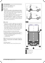
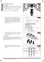
Fig. 5.11
Fig. 5.12
Fig. 5.13
Fig. 5.14
1 mm
Optional,
max 3 mm
8mm
2 mm
5.3 Using the Dahl Docking System
CAUTION!
The installation should be performed or supervised by a
technician. Read all instructions carefully before proceeding
with the installation.
To install Docking Plate use Dahl Adaption Kit #503259
1. Fit the 8 mm spacer onto the lock plate (Fig. 5.11).
3. Put the five screws through the lock plate, the mandatory
8 mm spacer and the selected optional spacers (gray in
picture) (Fig. 5.13).
WARNING!
Do not use any other screws than those supplied from Dahl
engineering (Part #502800 which is Quality 14.9 with Torx
Key Size 27). Standard screws will not be strong enough in the
event of a collision.
4. Mount the five screws together with the spacer/spacers
and the lock plate on the underside of the chassis box
(Fig. 5.14).
2. Use more spacers to achieve desired thickness with
regards to, for instance, user weight and tire pressure.
Additional spacers can be mounted under the locking
station (Fig. 5.12). To align the height of the lock plate
under wheelchair with the docking station fit spacers
between the docking station and the vehicle floor to raise
the docking station.
Mandatory

