background image


We value your experience using Sunny Health and Fitness products. For assistance with parts or 
troubleshooting, please contact us at [email protected] or 1-877-90SUNNY (877-
907-8669). 


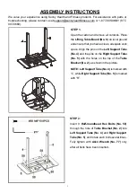
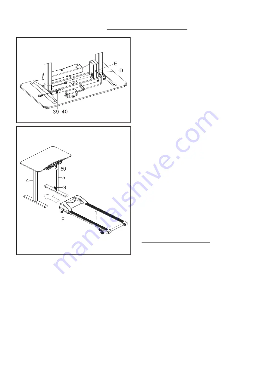
STEP 5: 

Connect the 

Lifting Table Power Cord (No. 39)


to the 

Power Adapter (No. 40)

Connect the plug (D) and plug (E) respectively. 

Pay attention to the direction. 


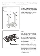
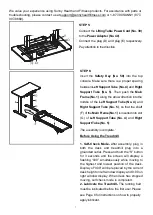
STEP 6: 

Insert th

Safety Key (No. 50) 

into the top 

console.  Make sure there is a proper spacing 

between 

Left Support Tube (No. 4) 

and 

Right 

Support Tube (No. 5)

. Then


push the 

Main 

Frame (No. 1) 

along the arrow direction into the 

middle of the 

Left Support Tube (No. 4) 

and 

Right Support Tube (No. 5)

, so that the shaft 

(F) of the 

Main Frame (No. 1) 

is inserted into slot 

(G) of 

Left Support Tube (No. 4) 

and 

Right 

Support Tube (No. 5)

.


The assembly is complete


Before Using the Treadmill 
 
1. Self-Check Mode-

 After assembly, plug in 

both the desk and treadmill plug into a 
grounded outlet. Press and hold the “S” button 
for 3 seconds and the screen will display a 
flashing “000” simultaneously while moving to 
the highest and lowest position of the desk. 
Display of “000” will be replaced by the current 
desk height on left window display and 0:00 on 
right window display. When desk has stopped 
moving, self check mode is completed. 

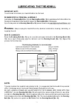
2. Lubricate the Treadmill- 

The running belt 

must be lubricated before the first use! Please 

see Page 8 for instructions on how to properly 

apply lubricant. 


Summary of Contents for SF-TD7884

Page 1: ...4 USER MANUAL IMPORTANT Please retain owner s manual for maintenance and adjustment instructions Your satisfaction is very important to us PLEASE DO NOT RETURN UNTIL YOU HAVE CONTACTED US support sunn...

Page 2: ...e equipment is designed for adult use only 4 Use the equipment on a solid flat level surface with a protective cover for your floor or carpet To ensure safety the equipment should have at least 8 feet...

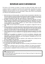
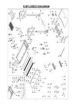
Page 3: ...2 EXPLODED DIAGRAM...

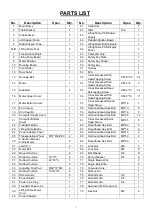
Page 4: ...End Cap L 1 58 Half roundhead Hex Bolt M6 10 8 19 End Cap R 1 59 Half roundhead Hex Bolt M6 16 5 20 Computer Upper Cover 1 60 Half roundhead Hex Bolt M6 30 12 21 Computer Bottom Cover 1 61 Cross Reces...

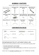
Page 5: ...ease provide the following information in order for us to accurately identify the part s needed The model number found on cover of manual The product name found on cover of manual The part number foun...

Page 6: ...a clean adequate work space Align the pins on the Left Support Tube No 4 and the pins on the Right Support Tube No 5 with the holes on the top of the Table Bracket No 2 as shown in the picture NOTE Le...

Page 7: ...the hexagon shaft B 45 mm inside the knob A Tighten the knob A clockwise Pull out the hexagon shaft C from the Transmission Shaft No 7 Insert it into the hexagon hole on the Left Support Tube No 4 45...

Page 8: ...e No 4 and Right Support Tube No 5 so that the shaft F of the Main Frame No 1 is inserted into slot G of Left Support Tube No 4 and Right Support Tube No 5 The assembly is complete Before Using the Tr...

Page 9: ...pe the lubricant over the Running Board No 13 Repeat this process for the other side The following timetable is recommended Light user less than 3 hours week every 2 months Medium user 3 5 hours week...

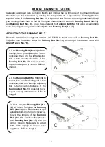
Page 10: ...ust the Running Belt No 13 according to instructions below with Allen Wrench No 76 1 If the Running Belt No 13 drifts to the right turn right adjusting bolt turn clockwise then turn the left adjusting...

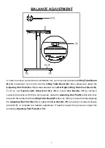
Page 11: ...To do so use Spanner with Screwdriver No 78 to loosen Hex Nut No 79 by turning it clockwise direction A With the nut loosened rotate the Adjusting Foot Pad No 33 until it sits level with the surface...

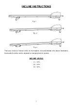
Page 12: ...NS There are 3 levels of manual incline on the treadmill As demonstrated in the above illustrations the treadmill s incline can be adjusted by changing the pin s position INCLINE LEVELS 1 0 0 2 2 9 3...

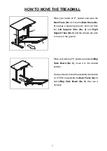
Page 13: ...from the Left Support Tube No 4 and Right Support Tube No 5 and the wheels are able to move on the ground Place your hands at K position and raise Lifting Table Board No 8 move it to the desired posit...

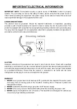
Page 14: ...codes and ordinances CAUTION Improper connection of the equipment can result in risk of electric shock Check with a qualified electrician or serviceman if you are unsure whether the product has been p...

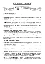
Page 15: ...eturn the Safety Key No 50 to console when 10 0 is displayed Note If treadmill is converted to Metric System speed and distance will be measured in Kilometers and Kimometers Hour FUNCTION KEYS MANUAL...

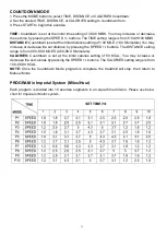
Page 16: ...1 00 MILE 1 00 Kilometers You may increase or decrease the set distance by pressing the SPEED buttons The DISTANCE setting range is from 0 00 99 9 MILES 0 00 99 9 Kilometers CALORIES Countdown is set...

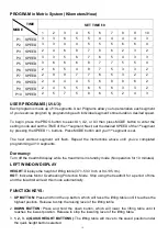
Page 17: ...uttons Press MODE button and your 1st segment is set The next workout segment will flash Repeat the instructions above until you ve completed programming all 10 segments Dormancy Turn off the treadmil...

Page 18: ...y learn the highest and lowest positions and display the normal position after self check Press and hold the S Button and the number button simultaneously to save the current position 6 RESISTING REBO...

Page 19: ...f 0 6 MPH 1 0 KM H Once you feel comfortable you may slowly increase the speed When you are finished with your exercise press the STOP button or remove the magnetic end of Safety Key No 50 to stop the...

Page 20: ...ny burning smell around the motor and control board Make sure the power and voltage comply with the standard as per manual Inspect all moving parts to ensure they are operating correctly Listen for un...

Page 21: ...20...
Reviews: