12
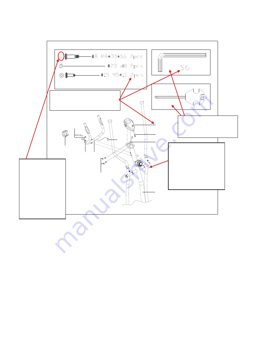
STEP: 6
Attach the
Middle Handlebar (No. 2)
to the clamp located on the
Handlebar Post (No.
64)
using 2
Screws (No. 8)
and 2
Spring Washers (No. 23)
, tighten with
Allen Wrench
S6 (No. 67)
, then cover the clamp using
Clamp Cover (No. 42)
.
Connect the
Upper Sensor Wire (No. 10)
to the
Computer Wire (No. 71)
. Then using
2
Screws (No. 15)
attach the
Computer (No. 1)
to the computer bracket located on the
top of
Handlebar Post (No. 64)
. Tighten with
Spanner (No. 68)
.
Insert the
Handle Pulse Wire (No. 9)
into the socket located on the back of the
Computer (No. 1)
. Assembly is complete!
2
23
15
8
10
9
64
42
71
1
Please revise the
quality
and
clarity
of
the drawing for this
STEP
Please make this
drawing darker
#68
#67
Please remove
the
Washer
from
the
Parts
shown
for this
Step
as
the
Washer
shown is
Part
(No. 23)
and
does not need to
be shown twice.
Please
ADD Part
Numbers (67 & 68)
to
the
Drawing
Please ensure that all
numbers for parts are
the same font
and size


