background image

9


STEP

 4

:  

Attach the 

Leg Developer (No. 9)

 to the 

Front Post (No. 5)

 using 1 

Hex Bolt (No. 25)

Washer (No. 31)

 and 1 

Aircraft Nut (No. 33)

. Tighten and secure with 

Spanner (No. 

14)

Insert the 

Foam  Roller  Bars (No.  7)

 through the holes located on the 

Leg Developer 

(No.  9)

.  Next,  attach  the 

Foam  Rollers  (No.  17)

  onto  each  end  of  the 

Foam  Roller 

Bars (No. 7)

.  

Lastly,  slide  the 

Spring  Clip  (No.  19)

  onto  the  bar  located  on  the  bottom  of  the 

Leg 

Developer (No. 9)

The assembly in complete! 

7

17

15

15

15

17

7

16

16

18

19

18

33

31

17

9

5

25

#25 (M10x2 3/8") 1pc

#31 (3/4")  (1pc)

#33 (M10)  (1pc)

17

Summary of Contents for SF-BH6811

Page 1: ... IMPORTANT Please retain owner s manual for maintenance and adjustment instructions Your satisfaction is very important to us PLEASE DO NOT RETURN UNTIL YOU HAVE CONTACTED US support sunnyhealthfitness com or 1 877 90 SUNNY 877 907 8669 ...

Page 2: ...d pets away from the equipment The equipment is designed for adult use only 4 Use the equipment on a solid flat level surface with a protective cover for your floor or carpet To ensure safety the equipment should have at least 4 feet 1 2m of free space all around it 5 Ensure that all nuts and bolts are securely tightened before using the equipment The safety of the equipment can only be maintained...

Page 3: ...EXPLODED DRAWING 1 13 21 1 6 18 18 20 21 13 2 31 33 33 31 33 31 12 8 11 10 29 26 26 29 22 3 5 4 7 9 17 15 15 15 17 7 16 16 18 19 18 28 30 30 32 32 16 33 31 23 24 27 29 17 20 20 25 31 33 26 29 15 8 17 2 ...

Page 4: ...COMPONENT PARTS LIST 3 ...

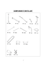
Page 5: ... 8 x 3 3 8 1 13 Bracket 4 3 4 x 3 1 2 2 14 Spanner 2 15 End Cap 3 4 4 16 End Cap 1 1 2 x 1 1 2 3 17 Foam Roll 4 18 End Cap 1 4 19 Spring Clip 1 1 20 End Cap 3 4 x 3 4 4 21 Carriage Bolt M10x2 5 8 4 22 Hex Bolt M10x2 1 8 2 23 Carriage Bolt M8x1 5 8 1 24 Carriage Bolt M8x1 3 4 1 25 Hex Bolt M10x2 3 8 1 26 Hex Bolt M6x1 3 8 4 27 Hex Bolt M6x5 8 4 28 Hex Bolt M8x2 1 8 1 29 Washer 1 2 8 30 Washer 5 8 3...

Page 6: ...n order for us to accurately identify the part s needed The model number found on cover of manual The product name found on cover of manual The part number found on the EXPLODED DIAGRAM and PARTS LIST found near the front of the manual Please contact us at support sunnyhealthfitness com or 1 877 90SUNNY 877 907 8669 5 ...

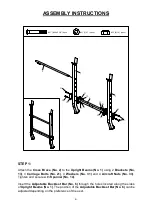
Page 7: ...Aircraft Nuts No 33 Tighten and secure with Spanner No 14 Insert the Adjustable Backrest Bar No 6 through the holes located along the sides of Upright Beams No 1 The position of the Adjustable Backrest Bar No 6 can be adjusted depending on the preference of the user 1 13 21 1 6 21 13 2 31 33 33 31 21 M10x2 5 8 4pcs 31 3 4 4pcs 33 M10 4pcs 31 33 33 31 21 ...

Page 8: ...pport No 3 and secure using 1 Washer No 30 and 1 Aircraft Nut No 32 Insert Carriage Bolt No 24 through the upper hole on the Main Seat Support No 3 Fix one end of the Diagonal Support No 4 to the Carriage Bolt No 24 using 1 Washer No 30 and 1 Aircraft Nut No 32 Fix the other end of the Diagonal Support No 4 to the Front Post No 5 using 1 Hex Bolt No 28 1 Washer No 30 and 1 Aircraft Nut No 32 Tight...

Page 9: ...n the top ends of the Backrest Supports No 8 against the Backrest Adjustment Bar No 6 Place the Backrest Board No 11 onto the Backrest Supports No 8 align the holes and secure the Backrest Board No 11 using 4 Washers No 29 and 4 Hex Bolts No 26 Tighten and secure with Spanner No 14 Attach the Seat Pad No 10 to the Main Seat Support No 3 using 4 Washers No 29 and 4 Hex Bolts No 27 Tighten and secur...

Page 10: ...t the Foam Roller Bars No 7 through the holes located on the Leg Developer No 9 Next attach the Foam Rollers No 17 onto each end of the Foam Roller Bars No 7 Lastly slide the Spring Clip No 19 onto the bar located on the bottom of the Leg Developer No 9 The assembly in complete 7 17 15 15 15 17 7 16 16 18 19 18 33 31 17 9 5 25 25 M10x2 3 8 1pc 31 3 4 1pc 33 M10 1pc 17 ...

Page 11: ... the incline or decline of the surface should be limited to 3 or less 2 Removing the weight plates not included Weight plates on the bar must be taken off in equal amounts at the same time in order to prevent the bar from becoming unevenly weighted which will cause the bar to tip It is strongly recommended that the bar be removed from the upright and placed on the ground whenever adding or removin...

Page 12: ...nd remove sweat and moisture after each use Perform inspection of all nuts and bolts associated with moving parts of the equipment tighten as required Check the mobility of moving parts and components on the equipment lubricate if required Clean plastic parts of the equipment using a damp cloth clean metal parts of the equipment using a dry cloth Do not use cleaning products to clean the equipment...

Reviews: