6
ASSEMBLY INSTRUCTIONS
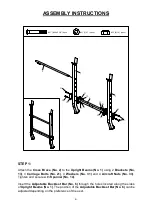
STEP
1
:
Attach the
Cross Brace (No. 2)
to the
Upright Beams (No. 1)
using 2
Brackets (No.
13)
, 4
Carriage Bolts (No. 21)
, 4
Washers (No. 31)
and 4
Aircraft Nuts (No. 33)
.
Tighten and secure with
Spanner (No. 14)
.
Insert the
Adjustable Backrest Bar (No. 6)
through the holes located along the sides
of
Upright Beams (No. 1)
. The position of the
Adjustable Backrest Bar (No. 6)
can be
adjusted depending on the preference of the user.
1
13
21
1
6
21
13
2
31
33
33
31
#21 (M10x2 5/8") 4pcs
#31 (3/4") (4pcs)
#33 (M10) (4pcs)
31 33
33
31
21
Summary of Contents for SF-BH6811
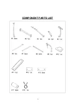
Page 4: ...COMPONENT PARTS LIST 3 ...


