background image

86

P

Prro

otto

oc

co

oll

D

De

essc

crriip

pttiio

on

n

FTP

The Logger4000 transfers the data of the collected

equipment (such as inverter, PV combiner box, Meteo

Station, etc.) to the remote monitoring system through

the FTP protocol.

MQTT

Logger4000 transfers the data collected from devices

(such as inverters, PV combiner box, Meteo Station,

etc.) to the remote monitoring system through the

MQTT protocol.

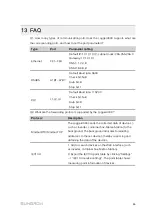
Q3. How to connect multiple Logger4000s to the background through the network?

1

Logger4000s closer to the Ethernet switch (<100m) are connected to the Ethernet

switch by using network cables.

2

Logger4000s relatively far away from the Ethernet switch (>100m) are connected

to the Ethernet switch by using routed fiber optic cables.

3

After cable connection, IP address of the multiple Logger4000s should be set to be

within the same network segment, without repeated addresses.

13 FAQ

User Manual

Summary of Contents for Logger4000

Page 1: ...at ta a L Lo og gg ge er rU Us se er r M Ma an nu ua allL Lo og gg ge er r4 40 00 00 0 U UE EN N V Ve er r1 11 1 2 20 02 21 11 10 0 Logger4000 UEN Ver11 202110 Logger4000 D Da at ta a L Lo og gg ge e...

Page 2: ......

Page 3: ...lation Flow 12 5 Unpacking and Storage 14 5 1 Scope of Delivery 14 5 2 Identifying the Logger4000 15 5 3 Checking upon Receiving 15 5 4 Storage 16 6 Mechanical Installation 17 6 1 Location Selection 1...

Page 4: ...Connection 40 8 Commissioning 42 8 1 Inspection before Commissioning 42 8 2 Commissioning Steps 42 9 Web Interface 44 9 1 Running Requirements 44 9 2 Login Steps 44 9 3 Web Main Interface 45 9 4 Opera...

Page 5: ...orwarding Configuration 57 9 9 10 IEC104 57 9 9 11 MODBUS 59 9 9 12 Third party portal 60 9 9 13 Forward GOOSE Service Configuration 61 9 9 14 Interface 61 9 9 15 MPLC 63 9 9 16 More 63 9 9 17 About 6...

Page 6: ...IV 14 Appendix A Technical Data 87 15 Appendix B Related Drawings 89 16 Appendix C General Information 90 16 1 Quality Guarantee 90 16 2 Contact Information 90...

Page 7: ...miliar with the PV grid connected power generation system and its working principle Have received professional training in installing and commissioning of the electrical devices Be capable of handling...

Page 8: ...e symbols used DANGER indicates a hazard with a high level of risk which if not avoided will result in death or serious injury WARNING indicates a hazard with a medium level of risk which if not avoid...

Page 9: ...written authorization of SUNGROW The content of the manual will be periodically updated or revised as per the product development It is probably that there are changes in manuals for the subsequent mo...

Page 10: ...work related safety warnings and notes will be specified at the critical points in corresponding chapter All operations and electrical work must only be performed by qualified personnel B Be ef fo or...

Page 11: ...s subject to the following two conditions 1 This device may not cause harmful interference and 2 This device must accept any interference received including interference that may cause undesired opera...

Page 12: ...ever replace the internal components of the Logger4000 without authorization SUNGROW shall not be held liable for any possible damage caused by ignorance of this warning 2 Safety Instructions User Man...

Page 13: ...4000 is designed with four Ethernet ports FE1 FE4 through which Logger4000 can realize data exchange It can be connected to SCADA or insight northward and to third party devices southward D Da at ta a...

Page 14: ...rmer meteo station and meter in the PV power generation system through RS485 bus and can also access the string inverter with PLC function produced by SUNGROW through PLC bus Logger4000 can transmit t...

Page 15: ...C Cllo ou ud d t th hr ro ou ug gh h a a r ro ou ut te er r As shown in the figure below the Logger4000 can be directly connected to the iSolarCloud through a router 3 3 Appearance 3 3 1 Appearance Ap...

Page 16: ...tu us s S St ta at tu us s D De es sc cr riip pt tiio on n PWR Power supply indicator On Normal power supply Off Abnormal power supply RUN Running indicator Blinking Normal operation Off On Abnormal...

Page 17: ...Na am me e S St ta at tu us s S St ta at tu us s D De es sc cr riip pt tiio on n FAULT Fault indicator On The inverter connected is faulty Off The inverter connected is not faulty 3 3 2 Dimensions Use...

Page 18: ...er r 1 Unpacking and inspection 5 1 Scope of Delivery 2 Read the user manual especially Safety Instructions 2 Safety Instructions 3 Store the Logger4000 properly if it is not to be installed immediate...

Page 19: ...Pr ro oc ce ed du ur re e R Re ef fe er re en nc ce e c ch ha ap pt te er r 7 Check before commissioning 8 1 Inspection before Commissioning 8 Commissioning 8 2 Commissioning Steps User Manual 4 Insta...

Page 20: ...uide quality certificate packing list product test report and warranty card C Communication terminal resistor Note if there are more than 15 devices connected on the RS485 bus it is recommended to con...

Page 21: ...right corner of the Logger4000 shown by A in the figure below The nameplate contains important parameters Ensure it is intact and clearly legible 5 3 Checking upon Receiving The Logger4000 is thorough...

Page 22: ...r Ambient temperature 40 to 70 relative humidity 0 95 no condensation Take precautions to protect the device against damage due to harsh environment such as shock cooling shock heating and collision R...

Page 23: ...in locations where children are likely to be present R Re eq qu uiir re em me en nt t f fo or r I In ns st ta alllla at tiio on n C Clle ea ar ra an nc ce e Reserve enough clearances around the Logge...

Page 24: ...per Wire cutter Tube crimp Slotted screwdriver M2 M6 Phillips M4 Rubber Goggles 6 3 Installing Logger4000 The Logger4000 can be installed anywhere in the room meeting the installation environment requ...

Page 25: ...Ea ar rs s a an nd d B Bo ot tt to om m S Su up pp po or rt te er rs s Anchor the mounting ears and bottom supporters to the Logger4000 with supplied M4x8 cross recessed countersunk head screws The fa...

Page 26: ...d installation Installation tools and component parts 1U standard rack beyond the scope of delivery Electric screwdriver beyond the scope of delivery Screw beyond the scope of delivery Nut beyond the...

Page 27: ...ions on the rack according to dimensions of the Logger4000 step 2 Drill holes on the rack with a hammer drill of 6mm step 3 Level the mounting ears with the drilled holes on the rack User Manual 6 Mec...

Page 28: ...22 step 4 Fix the Logger4000 in the sequence of screws mounting ears rack and nuts E En nd d 6 Mechanical Installation User Manual...

Page 29: ...PLC communication port immediately after powering down Wait at least 30s to have the capacitor discharge completely Do not enable the rated DC input and AC input to supply power at the same time Other...

Page 30: ...0 75mm2 outdoor anti ultraviolet wire Passive dry contact input port USB USB port Reserved Micro SD SD port Used for software programming this port is only available to SUNGROW technicians Debug Debug...

Page 31: ...7Vac 50 60Hz current 0 48A Grounding hole 1 1 5mm2 outdoor anti ultraviolet wire Connecting protective grounding cable L1 L2 L3 MPLC communication interface 0 5mm2 cable withstand voltage cable ground...

Page 32: ...RS485 shielded twisted pair STP to connect any RS485 port A1B1 A7B7 of the Logger4000 and the RS485 communication terminal of the inverter C Co on nn ne ec ct tiin ng g t to o a a S Siin ng glle e I...

Page 33: ...mmunication failure occurs Serial port parameters of each device on the RS485 bus should be consistent with those of the Logger4000 The serial port parameters include baud rate data bit stop bit and c...

Page 34: ...he communications cable connected to an RS485 port on Logger must be press fitted to cord end terminals of proper specification step 5 Connect the wiring terminal to the terminal A1B1 A7B7 of the Logg...

Page 35: ...end to the three phase ports of the circuit breaker Port L1 of Logger must be connected to phase A of the circuit breaker port L2 to phase B and port L3 to phase C The details are shown in the follow...

Page 36: ...e between the Logger4000 and the load should be greater than 20m that is the LV grid connection point should be more than 20m away from the nearest load distribution line The load includes air conditi...

Page 37: ...e RS485 port or the Ethernet port Specifically refer to the table below E En ne er rg gy y M Me et te er r C Co om mm mu un niic ca at t iio on n P Po or rt t P Po or rt t D De ef fiin niit tiio on n...

Page 38: ...ergy meter to the wiring area of the Logger4000 step 2 Strip the protection layer and insulation layer of the communication cable with a wire striper as shown in the figure below step 3 Assemble prope...

Page 39: ...e protection layer and insulation layer of the dry contact input signal cable with a wire striper as shown in the figure below step 2 Assemble proper cord end terminals to signal cable whose protectiv...

Page 40: ...tion layer and insulation layer of the dry contact output signal cable with a wire striper as shown in the figure below step 2 Assemble proper cord end terminals to signal cable whose protective layer...

Page 41: ...put signal cable with a wire striper as shown in the figure below step 2 Assemble proper cord end terminals to signal cable whose protective layer and insulation layer are stripped off and crimp them...

Page 42: ...rip the protection layer and insulation layer of the signal cable for temperature detection with a wire striper as shown in the figure below step 2 Assemble proper cord end terminals to signal cable w...

Page 43: ...Ethernet ports FE1 FE4 The function of the ETH1 is reserved Access the Ethernet switch and the router through either port This section takes connecting to an Ethernet switch as an example to illustrat...

Page 44: ...to a power source with voltage ranging from 100 to 277Vac step 1 Lead the external power supply cable to the wiring area of the Logger4000 step 2 Strip off the protective layer and insulation layer o...

Page 45: ...step 1 Lead the external power supply cable to the wiring area of the Logger4000 step 2 Strip off the protective layer and insulation layer of the power cable with wire strippers as shown below step 3...

Page 46: ...device may be damaged due to lightning step 1 Strip the protection layer and insulation layer of the grounding cable by specific length as shown in the figure below step 2 Select proper OT terminal a...

Page 47: ...N No o D De es sc cr riip pt tiio on n N No ot te e A Bolt M4 B OT terminal C Grounding hole step 4 Fasten the screw with a wrench by the torque of 5 1N m E En nd d User Manual 7 Electrical Connectio...

Page 48: ...er4000 flickers normally 4 Log in to 12 12 12 12 through Internet Explorer Safari or Chrome 5 Configure serial port parameters on the Web interface 6 Add PV devices connected to Logger4000 to the Web...

Page 49: ...after downloading and installing the App 1 Log in to the Web of Logger4000 and click About to get the QR code 2 Scan the QR code with iSolarCloud App or manually enter the serial number S N to add co...

Page 50: ...rnet port log in through the virtual IP The virtual IP of Ethernet port is 14 14 14 14 step 4 Select the desired language in the upper right corner of the interface and click Login User types include...

Page 51: ...a Display the current interface C Alarm icon Display the current alarm level and alarm number Users can click the icons to enter the corresponding alarm interface D Help Display the basic configuratio...

Page 52: ...7 1 Device List step 5 Configure forwarding service After all devices have been added configure the forwarding service of the Logger4000 to ensure that the Logger4000 can forward the data to upstream...

Page 53: ...to view the device fault information Information such as device name alarm name alarm type alarm time fault code and fault ID can be viewed 9 6 Device Monitoring Click Device Monitoring to enter the c...

Page 54: ...e single device E En nd d 9 6 3 2 Batch setting step 1 Select the desired country region and grid type step 2 Click Configure synchronization step 3 Select the desired devices in the pop up device lis...

Page 55: ...E En nd d 9 6 7 Protection Parameters Others step 1 Click Device Monitoring Protection Parameters Others to enter the interface step 2 Set the parameters according to the setting range Configure the...

Page 56: ...ponding interface On this interface users can boot shutdown the device or reset all settings Device instruction can be set in two manners single setting and batch setting Take the boot operation as an...

Page 57: ...E En nd d Inverters without the SN do not support the automatic search function and device adding function Automatic address allocation pops up only when there is an actual address confrontation 9 7 1...

Page 58: ...e device from the device list to keep device consistency step 1 Click Device Device list to enter the corresponding interface step 2 Select the device to be deleted click the button Delete step 3 Clic...

Page 59: ...ces need to self checking click Self checking and then click Confirm on the pop up dialog The status of devices need to self checking must be Enable If the status is Disable click to set it to Enable...

Page 60: ...E En nd d 9 9 4 Rebooting step 1 Click System System maintenance to enter the corresponding interface step 2 Click Rebooting to enter the corresponding interface step 3 A warning window will pop up an...

Page 61: ...other regions select the International Server 9 9 7 Message Export step 1 Click System Message export to enter the corresponding interface step 2 Set parameters including interface serial port and dur...

Page 62: ...ne in the following two manners Select Use PC time to synchronize the time of the Logger4000 with the time of the PC Click the Time zone pull down list and select the local time zone Enter the Date an...

Page 63: ...unication protocol and otherwise this manner is invalid iSolarCloud Ensure that Logger4000 is connected to iSolarCloud Otherwise setting the clock source to iSolarCloud is invalid MODBUS TCP Ensure th...

Page 64: ...fault IEC104 point table will be automatically imported to configuration file E Ed diit t I IE EC C1 10 04 4 F Fo or rw wa ar rd diin ng g P Po oiin nt t T Ta ab blle e step 1 Click Export of Configur...

Page 65: ...oint table referring to Edit IEC104 Forwarding Point Table step 2 Click Add to enter the Advanced Settings interface step 3 Enter the port number of the server and the peer port and select the remote...

Page 66: ...very step 1 Click System Transfer Configuration MODBUS to enter the Server tab by default step 2 Click RTU to enter the corresponding tab step 3 Select serial port and enter delay time step 4 Click E...

Page 67: ...ports COM1 COM7 and 1 PLC port 9 9 14 1 RS485 step 1 Click System Interface RS485 to enter the corresponding interface step 2 Click to modify baud rate parity bit and stop bit S Se er riia all P Po or...

Page 68: ...nput type set the lower limit and upper limit and click the button to save the operation A AI I P Po or rt t I In np pu ut t T Ty yp pe e L Lo ow we er r S Sa am mp plliin ng g L Liim miit t U Up pp p...

Page 69: ...e step 1 Click System Port Parameters More to enter the interface step 2 Select automatic online state enable disable from the drop down list When the state is set to Enable parameters of string inver...

Page 70: ...2 1 Active Power 10 2 1 1 Disable If the inverter needs to operate at full load the active control mode should be set to Disable step 1 Click Power control Active power to enter the active power inter...

Page 71: ...get value active power of the meter needs to be collected and used as input parameter and active power compensation ratio is calculated and sent to the power output port of the inverter Generally this...

Page 72: ...The parameters noted with refer to the parameters that need to be set only when the Control Method is set to Closed loop Control step 4 After finishing parameter setting click Save to save the operati...

Page 73: ...e active power of the meter needs to be collected and used as input parameter and active power compensation ratio is calculated and sent to the power output port of the inverter Generally this strateg...

Page 74: ...and sent to the power output port of the inverter Generally this strategy is used for fast and accurate active power regulation In case a Smart Energy Meter is selected active instruction controlled b...

Page 75: ...e er r D De es sc cr riip pt tiio on n Control method Open loop control Active instruction controlled by DI is sent to the power output port of the inverter thereby achieving active power control Clos...

Page 76: ...r select a digital input manner that needs to be deleted and click Clear data 10 2 1 6 Country Mode If the dispatching input must be the national power dispatching instruction the active control mode...

Page 77: ...ime calibration Calibrate the time as needed Calibration range 10 10 When the system time of Logger4000 the time adjusted after Time calibration or the time of Logger1000 the NTP synchronization time...

Page 78: ...patching is sent to the power output port of the inverter thereby achieving active power control Closed loop control Remote monitoring background is connected and reactive instruction of remote dispat...

Page 79: ...reactive power direction Control cycle Time interval of delivering dispatching instructions Parameter range 5 60s Note The parameters noted with refer to the parameters that need to be set only when t...

Page 80: ...ity output Communication is abnormal and specified dispatch output value is delivered Wiring mode Direct connection One Logger4000 is connected to all inverters where all the inverters must be string...

Page 81: ...ulated and sent to power output port of the inverter Generally this strategy is used for improving the power factor of the property boundary point Select energy meter Select Smart Energy Meter involve...

Page 82: ...rt of the inverter thereby achieving active power control Closed loop control Reactive instruction controlled by DI is used as target value and reactive power and power factor of the meter need to be...

Page 83: ...control mode to Scheduling prohibited if the Logger4000 is prohibited to perform reactive dispatching on the inverter step 1 Click Power control Reactive power to enter the reactive power interface st...

Page 84: ...ibed in this chapter Do not leave any screws washers or other metallic parts inside the Logger4000 to avoid device damage After the Logger4000 stops wait at least 5 minutes before performing any work...

Page 85: ...ounding cable is grounded properly System cleaning Clean the enclosure circuit board and the components Check the heat dissipation hole and the ensure it is not covered Terminal and cable connection C...

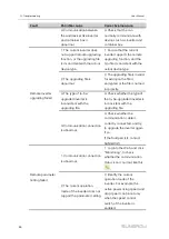
Page 86: ...pe configuration and other information of device connected to the Logger4000 Fault information and brief description Picture of the fault if possible F Fa au ullt t P Po os ss siib blle e c ca au us s...

Page 87: ...he Logger4000 and devices connected to it 1 The RS485 cable connecting the device and the Logger4000 is abnormal 1 Check the RS485 cable connecting the device and the Logger4000 and ensure it is not i...

Page 88: ...erse connection between RS485 A and RS485 B 2 COM port parameter is incorrectly set on the web interface 2 Log into the Web and click System Transfer Configuration Modbus RTU to check whether the COM...

Page 89: ...4 1 Network connection between the and background is incorrect 1 Check that the network connection between the and the background is correct 2 IP address of the forwarding device or background IP addr...

Page 90: ...pted or the file is named incorrectly 3 The type of to be upgraded inverter is inconsistent with the upgrading file 3 Check whether the type of the to be upgraded inverter is inconsistent with the upg...

Page 91: ...Check bit Null Data bit 8 Stop bit 1 Q2 What are the forwarding protocols supported by the Logger4000 P Pr ro ot to oc co oll D De es sc cr riip pt tiio on n ModbusRTU ModbusTCP The Logger4000 sends...

Page 92: ...to the remote monitoring system through the MQTT protocol Q3 How to connect multiple Logger4000s to the background through the network 1 Logger4000s closer to the Ethernet switch 100m are connected to...

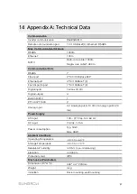
Page 93: ...X Fast dispatch port 1 10 100BaseT X Digital inputs 16 max 24 Vdc Digital outputs 4 Built in MPLC 1 PT100 PT1000 2 Analog Input 4 1 Analog input 0 10 Vdc 3 Analog input 4 20 mA P Po ow we er r S Su up...

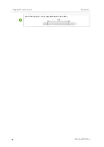
Page 94: ...88 Bind three phase cables together every one meter 14 Appendix A Technical Data User Manual...

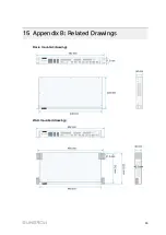
Page 95: ...89 15 Appendix B Related Drawings R Ra ac ck k m mo ou un nt te ed d d dr ra aw wiin ng gs s W Wa allll m mo ou un nt te ed d d dr ra aw wiin ng gs s...

Page 96: ...ersons not from SUNGROW The fault or damage caused by using non standard components or software or using components or software not from SUNGROW The installation and operation do not comply with stipu...

Page 97: ...rance Lyon 33420102107 service sungrow emea com G Ge er rm ma an ny y A Au us st tr riia a S Sw wiit tz ze er rlla an nd d Sungrow Deutschland GmbH Munich 49 0 89 1307 2620 service sungrow emea com G...

Page 98: ...mea com T Tu ur rk ke ey y Sungrow Deutschland GmbH Turkey Istanbul 90 216 663 61 80 service sungrow emea com U UK K Sungrow Power UK Ltd Milton Keynes 44 0 01908 414127 service sungrow emea com U U S...

Reviews: