11
12
Appendix II : Remote Control Coding
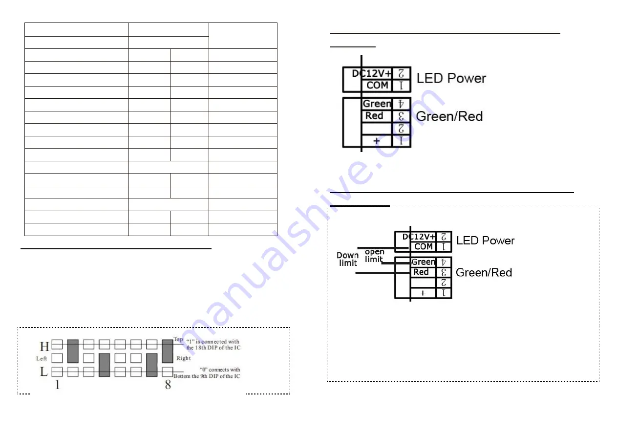
When you need to add remote remote controller, please coding the
new remote controller code same as previous ones.
Coding method: open the remote controller, take out the battery,
there is dial plate, the direction is from right to left. The solder
between middle port and top port is state “1”. The solder between
middle port and bottom port is state “0”. Empty is state “X”. The
code as below is
10XX0X1X (Warning: please take out the battery before coding!).
Appendix III: Wiring Diagram for R&G Light
Interface
Appendix IV: Wiring Diagram for up and down
limit output
No need Power
Boom Length(Meter: M)
Spring Diameter
Φ (mm)
Suggested max
speed
Straight Boom
Link Hole Selection
2≥L≥2.5
empty
3.5
0.6
4≥L≥3
empty
4.5
0.9
4.5≥L>4
3.5
4.5
1.2
6≥L>4.5
4.5
4.5
2
Folding arm
2≥L≥2.5
1.5
4≥L≥3
1.8
4.5≥L>4
1.8
6≥L>4.5
2
2-Fence Boom
4>L≥3
4.5
4.5
2
4.5≥L≥4
5.5
5.5
2.5
3-Fence Boom
3≥L≥2
4.5
4.5
2
4≥L>3
5.5
5.5
3


