5
6
6.Mechanical Part Installation and Adjustment
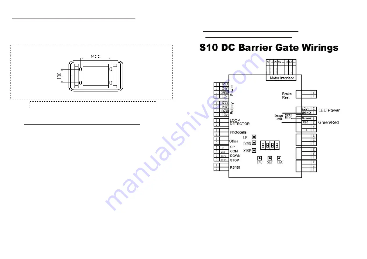
6.1. Installation of cabinet
Please select the correct type of barrier ate according the specifications
of the place, and then fix the barrier cabinet with expansion bolts.
(refer to Figure 3)
6.2. Spring selection, installation and adjustment
The barrier gate is well-adjusted before delivery. If need to cut the
boom shorter, please re-adjust the spring balance to ensure the
smooth operation of the barrier. Also you can adjust the speed to
slower or faster when arm made longer or cut shorter
6.2.1. Spring selection
The length of spring prevails in kind, designing change without
notice. The spring selection please refer to the spring selection
table in the
Appendix I
of the Manual or which sticks on the door
of the barrier cabinet.
6.2.2. Spring installation, dis-assembly and replacement
Dismantlement steps: Keep the boom at vertical (open) position, see
figure1, loosen the spring fixing nuts on the bottom of the spring by
adjustable or 8
th
spanner, unscrew the fastening wing nuts in the
bottom of the spring by manual, then take off the spring.The steps for
installation and dis-assembly the spring are the opposite.
6.2.3. Spring force adjustment
When power off, adjust the springs balance to make sure the arm will stay
in the angle 45-60 degrees towards the horizontal, and not going down or
going up, which mean the spring force is well balanced.
7.
Controller Wiring and Instructions
7.1.
Controller interface explanations
(Figure 4)
All the electrical connections are done before delivery. The necessity
is to connect the power and grounding connection. Explanations and
instructions for the main function interfaces and indicator light is as
following:
7.1.1. 220V/110V Power supply DIP switch in power supply:
This barrier motor supports 24VDC power input, and controller support
12V DC power input. There are two power supplies, one is 220V or
110V input(by DIP switch) while output is 24V DC, and another input is
110~220V AC while output is 12V DC. So one is for motor power
supply, and another is for control board power supply. the DIP switch is
Expansion Bolts
Press bars
(According to the supplementary size)
(According to the supplementary size)
(Figure 3)


