background image

Bi-spectrum network camera 
User Manual 


Other Web Configurations 

Issue V 1.1

2022-05-07

                                                                                                                              103


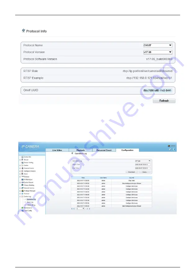
Figure 9-9


Protocol interface 


9.9   Device Log 

Choose

 configuration > device log. 

You can view 

operation log

 and 

alarm log

, or 

collect all log information, as shown in Figure 9-10. 

Figure 9-10


Device log interface 


9.10 Maintenance   

Choose

 configuration > maintenance. 

You can 

restart, update, reserve IP setting and 

restore to factory default

, as shown in Figure 9-11. 

Summary of Contents for SN-TPC2552DT-F

Page 1: ...Bi spectrum Network Camera User Manual Issue V 1 0 Data 2022 05 07 ...

Page 2: ......

Page 3: ...rs which if not avoided may cause deaths or severe injuries It alerts you to moderate dangers which if not avoided may cause minor or moderate injuries It alerts you to risks Neglect of these risks may cause device damage data loss device performance deterioration or unpredictable results It provides a tip that may help you resolve problems or save time It provides additional information To preven...

Page 4: ...ns of the thermal imaging camera The sun shade must be installed and adjusted according to the angle of the sunlight illumination Avoid heavy loads intensive shakes and soaking to prevent damages during transportation and storage The warranty does not cover any device damage that is caused during secondary packaging and transportation after the original packaging is taken apart This device is a st...

Page 5: ... artificial damage of the fragile sticker Special Announcement All complete products sold by the manufacturer are delivered along with nameplates operation instructions and accessories after strict inspection The manufacturer shall not be held responsible for counterfeit products This manual may contain misprints technology information that is not accurate enough or product function and operation ...

Page 6: ... Homepage Layout 14 2 3 Changing the Password 16 2 4 Browse Video 17 2 4 1 Install Plugins 18 2 5 Personnel Count 19 2 6 Setting Local Network Parameters 20 3 Temperature Measurement 24 3 1 Temperature Parameters 24 3 2 Ambient Temperature 30 3 3 Temperature Area 30 3 4 Shield Area 35 3 5 Schedule Linkage 36 3 6 Thermal Mapping 38 3 7 Bad Point Check 40 3 8 LED Control Param 42 3 9 Digital Tube 43...

Page 7: ...docolor 65 5 6 FFC Control 66 5 7 Noise Reduction 69 6 Intelligent Analysis 71 6 1 Perimeter 71 6 2 Single Virtual Fence 75 6 3 Double Virtual Fences 77 6 4 Personnel Count 79 6 5 Enter Area 83 7 AI Multi object 85 8 Alarm Setting 87 8 1 Alarm Output 87 8 2 Disk Alarm 88 8 3 Network Alarm 88 8 4 I O Alarm Linkage 89 8 5 Motion Alarm 90 8 6 Push Message 91 8 7 Sound Alarm Output 92 8 8 Audio Abnorm...

Page 8: ... V 1 1 2022 05 07 9 2 3 Snapshot 98 9 3 Device 99 9 4 External Device 99 9 5 Privacy Masking 101 9 6 Network Service 101 9 7 Privacy Manager 101 9 8 Protocol 102 9 9 Device Log 103 9 10 Maintenance 103 9 11 Local Config 104 9 12 QOS 105 A Troubleshooting 107 ...

Page 9: ... can be widely used in important fields such as airports stations urban roads traffic surveys corporate security warehouse monitoring and residential security 1 2 Features Using the uncooled infrared focal plane sensor Detecting the infrared wavelength ranging from 8 um to 14 ums High thermal sensitivity reaching 50 mK Supporting dedicated lens for 8 15 25 35 50 mm focal distance optional Supporti...

Page 10: ...ing bidirectional voice talkback Providing software and hardware watchdogs and automatic fault recovery Linked heat dissipation structure of the metal enclosure DC 12 V POE 1 3 Device Dimension Figure 1 1 shows the dimensions of device Figure 1 1 Dimensions unit mm 273 303 Adjustable 107 275 70 95 70 100 98 4 φ 4 5 30 2 1 4 U N C x 8 1 4 Installation Step 1 Stick the installation location sticker ...

Page 11: ...his step before mount is highly suggested to make it convenient to use electric screwdriver as shown in Figure 1 2 Figure 1 2 Adjust direction Screw 1 Step 3 Install the camera on the ceiling or wall and fixe the screws as shown in Figure 1 3 Figure 1 3 Fix camera Step 4 Connect the multi connector cable and monitor loosen the screw 2 to adjust the position so that the camera face the monitored ar...

Page 12: ...022 05 07 the screw 1 and screw 2 Figure 1 4 Adjust image Screw 2 Screw 1 1 5 Cable Connection Figure 1 5 the multi connector combination cable of the thermal imaging integrated network camera For details about the multi connector combination cable please refer to Table 1 1 ...

Page 13: ...o Connect the BNC connector 2 DC12V 2A Power interface connects to the 12 V DC power supply 3 Audio Input Inputs the audio signal and receives the analog audio signals from the sound pick up device 4 Audio Output Connects to the external audio device such as the voice box 5 Network interface Connects to the standard Ethernet cable 6 ALARM 2 Alarm in alarm out 2 Orange alarm OUT COM 2 Yellow alarm ...

Page 14: ...ew User Manual 12 Issue V 1 1 2022 05 07 Grey alarm IN COM 2 Purple alarm IN 2 7 ALARM1 Alarm in alarm out 1 Brown alarm OUT COM 1 Blue alarm OUT 1 White alarm IN COM 1 Green alarm IN 1 8 RS485 RS485 interface connects to the external pan tilt ...

Page 15: ...68 0 121 in the address box and press Enter The login page is displayed as shown in Figure 2 1 Figure 2 1 Login page Step 2 Input the user name and password The default name and password both are admin Modify the password when you log in the system for first time to ensure system security After modifying password you need to wait at least three minutes then power off to make sure modifying success...

Page 16: ...hown the homepage layout Table 2 1 lists the elements on the homepage layout Figure 2 2 Homepage layout Table 2 1 Elements on the homepage NO Element Description 1 Real time video area Real time videos are played in this area You can also set sensor parameters The two channels are displaying at the same time 2 Playback You can query the playback videos in this area 3 Configuration You can choose a...

Page 17: ...nfigurationThermal Sensor Configuration5 Thermal Sensor ConfigurationThermal Sensor ConfigurationThermal Sensor ConfigurationThermal Sensor ConfigurationThermal Sensor Configuration Snapshot Record video to local storage Intelligent analysis Choose the stream to stream 2 click to open the intelligent analysis it will show target information and video stream draw line after you have turned on the f...

Page 18: ...splayed as shown in Figure 2 3 Figure 2 3 Change password dialog box The change password page will be displayed if you don t change the default password when you login the system for the first time Step 2 Input the old password new password and confirm password Step 3 Click OK If the message Change password success is displayed the password is successfully changed If the password fails to be chang...

Page 19: ...in to the web for the first time Step 1 Open the Internet Explorer Choose Tools Internet options Security Trusted sites Sites In the display dialog box click Add as shown in Figure 2 4 Figure 2 4 Adding a trusted site Step 2 In the Internet Explorer choose Tool Internet Options Security Customer level and set Download unsigned ActiveX control and initialize and script ActiveX controls not marked a...

Page 20: ...s prompted The login page is displayed when the control is loaded If you can view the live video immediately you can ignore the steps of adding trust site 2 4 1 Install Plugins You will be prompted with a message click here to use short delay Plugin for Live Video as shown in Figure 2 6 when you log in to the web management system for the first time Figure 2 6 Download the plugin page ...

Page 21: ...l During installing plugins you need to close the browser finish the installation login the device again End 2 5 Personnel Count At personnel count interface you can view the personnel count throughout setting query condition choose the detail time at date s pop up window There are three modes to show the data such as line chart histogram and list as shown in Figure 2 7 Figure 2 7 Personnel count ...

Page 22: ...g Local Network Parameters Description Local network parameters include IP protocol IP address Subnet mask Default gateway Dynamic Host Configuration Protocol DHCP Preferred Domain Name System DNS server Alternate DNS server MTU Procedure Step 1 Choose Configuration Device Local Network The Local Network page is displayed as shown in Figure 2 8 ...

Page 23: ...meter Description Setting IP Protocol IPv4 is the IP protocol that uses an address length of 32 bits Setting method Select a value from the drop down list box Default value IPv4 DHCP The device automatically obtains the IP address from the DHCP server Setting method Click the option button NOTE To query the current IP address of the device you must query it on the platform based on the device name...

Page 24: ...nually Default value 192 168 0 1 Alternate DNS Server IP address of a domain server If the preferred DNS server is faulty the device uses the alternate DNS server to resolve domain names Setting method Enter a value manually Default value 192 168 0 2 MTU Set the maximum value of network transmission data packets Setting method Enter a value manually NOTE The MTU value is range from 1280 to 1500 th...

Page 25: ...ration Issue V 1 1 2022 05 07 23 If you set only the Subnet Mask Default Gateway Preferred DNS Server and Alternate DNS Server parameters you do not need to login to the system again You can click Reset to restore the previous parameters if required End ...

Page 26: ...ure parameters include temperature unit ambient type ambient temperature cavity temperature correctional coefficient area temperature display mode area temperature type measure mode and area alarm interval Operation Procedure Step 1 Choose Configuration Thermal Temperature Parameters The Temperature Parameters page is displayed as shown in Figure 3 1 ...

Page 27: ... 1 Temperature Parameters interface Step 2 Set the parameters according to Table 3 1 Table 3 1 Temperature parameters Parameter Description Setting Temperature Unit Celsius and Fahrenheit temperature units are available Setting method Select a value from the drop down list box Default value Celsius ...

Page 28: ...n coefficient should be 0 5 2 The measured object temperature is 37 3 and actual temperature is 36 5 so the correction coefficient should be 0 8 NOTE User should contact the technical support staff of our company at this condition to make sure to apply Setting method Enter a value manually Default value 0 00 Area ID display mode There two mode to display area ID and area name Setting method Select...

Page 29: ...l Display Alarm Area N A Setting method Enable or disable Default value Disable Area Alarm Interval 1 1800s N A Setting method Enter a value manually ranges from 1 to 1800 Default value 10 Area Alarm delay 0 10sec N A Setting method Enter a value manually ranges from 1 to 10 Default value 0 Temperature range It depends on the device Different devices have different modes there are two ranges such ...

Page 30: ...manual the user should choose the action manually such as pick up lay down Setting method Select a value from the drop down list box Figure 3 2 Advanced interface Table 3 2 Advance parameters Parameter Description Setting Dimming Mode There are auto and manual modes It will show on temperature item Setting method Select a value from the drop down list box Default value Auto Greater Prominent Enabl...

Page 31: ...anually Choose one color to show Less Prominent Enable that the image will show the setting color if the temperature is lower than set value Setting method Enter a value manually Choose one color to show Raw Data Upload Interval F S Interval of Uploading the raw data Setting method Select a value from the drop down list box Default value 1 Mix Stream Mode This function is used for thermal and visi...

Page 32: ...ing Ambient Temperature Environment temperature of camera Setting method Enter the temperature of ambient Default value 25 Adaptation environment temperature Set the ambient temperature click Apply click Refresh the camera will get the value automatically End 3 3 Temperature Area Operation Procedure Step 1 Choose Configuration Thermal Temperature Area The Temperature Area page is displayed as show...

Page 33: ...cording to Table 3 4 Table 3 4 Temperature area and alarm configuration Parameter Description Setting Channel Channel 1 is visible light channel Channel 2 is thermal channel Setting method Select a value from the drop down list box Default value 2 Measure Mode Set at temperature parameter interface N A Enable Tick the ID to enable the area measuring Setting method Tick ...

Page 34: ...lue is more than the set value it will generate the alarm Setting method Select a value from the drop down list box Default value Threshold alarm Warning Value Camera will trigger warning alarm when the object temperature reaches the warning value Setting method Enter a value manually Default value 48 Alarm Value Camera will alarm when the object temperature reaches the alarm value Setting method ...

Page 35: ...tance between camera and target Setting method Enter a value manually Default value 15 Enter actual distance when the distance between camera and target is less than 15m Enter 15 when the distance between camera and target is great than or equal to 15m Alarm Enable or disable the alarm output and linkage of area Setting method Tick the alarm output channel Step 3 Set temperature area Tick an area ...

Page 36: ... displayed the temperature area is set successfully NOTE ID 0 is the full screen the area cannot be changed the lowest temperature of the full screen the highest temperature of the full screen the lowest temperature of the area the highest temperature of the area Delete a temperature area Select an area ID Click the temperature area and right click Remove the tick of area ID ...

Page 37: ...3 4 Shield Area Shield area is meaning that the camera will do not detect the temperature of that area The shield areas can be set up to four areas Operation Procedure Step 1 Choose Configuration Thermal Shield Area Figure 3 6 Shield Area Step 2 Enable the shield area Step 3 Enable Show Shield Area then the setting shield will show on live video Step 4 Click left mouse button to set area click rig...

Page 38: ...Linkage page is displayed as shown in Figure 3 7 Tick the output channel if user connects the external alarm device It can also enable alarm record SMTP FTP upload audio alarm and flashlight alarm Figure 3 7 Schedule Linkage Step 2 Tick the output channel Enable alarm record SMTP FTP upload and audio alarm The audio alarm file will be set at Alarm Sound Alarm Output interface as shown in Figure 3 ...

Page 39: ...d alarm output User can set the audio file manually Click to upload the audio file the type should be WAV as shown in Figure 3 9 Figure 3 9 Upload audio file Step 3 Set schedule linkage Method 1 Click left mouse button to select any time point within 0 00 24 00 from Monday to Sunday as shown in Figure 3 7 ...

Page 40: ...o delete the selected alarm time Step 4 Click Apply The message Apply success is displayed the system saves the settings There are six types schedule linkage to set like threshold alarm threshold warning temperature difference alarm temperature difference warming temperature section alarm temperature rise alarm and temperature rise warning End 3 6 Thermal Mapping NOTE The images have been calibrat...

Page 41: ...hermal mapping Parameter Description Setting Zoom in zoom out Setting method Click the button Near focus far focus Setting method Click the button Lock focus position N A Setting method Tick Horizontal shift Adjust horizontal position of area which is on visual image Setting method Input value Vertical shift Adjust vertical position of area which is on visual image Setting method Input value ...

Page 42: ...nal display of the picture Point one is green cross Point two is red cross Point three is blue cross Setting method Select from drop list Step 3 Click Apply The message Apply success is displayed the system saves the settings End 3 7 Bad Point Check Operation Procedure Step 1 Choose Configuration Thermal Bad Point Check The Bad Point Check page is displayed as shown in Figure 3 11 If the image has...

Page 43: ...trum network camera User Manual Temperature Measurement Issue V 1 1 2022 05 07 41 Figure 3 11 Bad Point Check Step 2 Click the white point at image click Reset to recover the bad point as shown in Figure 3 12 ...

Page 44: ...t User Manual 42 Issue V 1 1 2022 05 07 Figure 3 12 Recover bad point Step 3 Click Apply The message Apply success is displayed the system saves the settings End 3 8 LED Control Param Set the display mode and brightness of LED as shown in Figure 3 13 ...

Page 45: ...e are four modes can be chosen Open the LED is always lighting Close the LED is closed Flicker set the flicker interval the LED will flicker as the set Timing the LED will lighting at the set time Setting method Select from drop down list Brightness The LDE s brightness Setting method Drag the slider Default value 100 End 3 9 Digital Tube Set the digital tube parameters as shown in Figure 3 14 ...

Page 46: ...l tube Parameter Description Setting Enable Enable it the digital tube will show the temperature of detecting Default value Enable Relate Area ID It is relativity to the Area ID of Parameter Configure choose one ID the tube will show the highest temperature of that area Setting method Select from drop down list Default value 1 End ...

Page 47: ... Configuration 4 1 Accessing the Sensor Interface Procedure Step 1 On the web move the cursor to the real time video page and right click on the page A shortcut menu is displayed as shown in Figure 4 1 Figure 4 1 Sensor setting interface Or at Configuration Sensor Setting interface to set as shown in Figure 4 2 ...

Page 48: ...etting Step 2 Choose Sensor Configure and the Sensor Setting dialog box appears All sensor configure can be modified at debug mode Click in the lower left corner of Sensor Setting and choose Debug Mode End 4 2 Mode Step 3 Click in the lower left corner of Sensor Setting and choose Debug Mode As shown in Figure 4 3 ...

Page 49: ...22 05 07 47 Figure 4 3 Mode Step 4 Choose the switch mode from the drop down list Step 5 Time mode Set the Start Time set the End Time Step 6 Click Save the message Save succeed is displayed the system saves the settings End 4 3 Image Adjust Figure 4 4 shows the Image Adjust tab page ...

Page 50: ... Image Parameter Description Configuration Method Brightness It indicates the total brightness of an image As the value increases the image becomes brighter Setting method Drag the slider Default value 50 Sharpness It indicates the border sharpness of an image As the value increases the borders become clearer and the number of noise points increases Setting method Drag the slider Default value 50 ...

Page 51: ... Default value 50 Contrast It indicates the measurement of different brightness levels between the brightest white and darkest black in an image The larger the difference range is the greater the contrast the smaller the difference range is the smaller the contrast Setting method Drag the slider Default value 50 End 4 4 Scene Figure 4 5 shows the scene tab page Figure 4 5 Scene Table 4 2 describes...

Page 52: ... a value from the drop down list Default value Indoor Mirror It is used to select the pixel location of an image Normal The image does not flip Horizontal The image flips to the left and right Vertical The image flips up and down Horizontal Vertical The image rotates at 180 degrees Setting method Select a value from the drop down list Default value Normal End 4 5 Exposure Figure 4 6 shows the Expo...

Page 53: ...ting Parameter Description Configuration Method Exposure Mode The exposure modes include Auto The system performs auto exposure based on the monitoring environment Manual You can set Shutter Setting to fixed values manually Shutter Priority You can set Shutter Setting to fixed values The shutter and gain are automatically adjusted by the system Setting method Select a value from the drop down list...

Page 54: ...It is valid in Iris Priority mode You can select a maximum shutter speed As the value increases the image becomes brighter Setting method Select a value from the drop down list Default value 1 25 Max gain It indicates the maximum gain The device automatically adjusts the gain based on the external light and the gain is less than or equal to the value of this parameter Setting method Drag the slide...

Page 55: ...Bi spectrum network camera User Manual Visible Sensor Configuration Issue V 1 1 2022 05 07 53 Figure 4 7 WB Table 4 4 describes the parameters on the WB tab page ...

Page 56: ...itoring scenario when the color temperature changes Auto camera adjusts automatically Tungsten at tungsten lamp Environment Fluorescent fluorescent environment Daylight at daylight environment Shadow at low light environment Manual adjust red and blue gain manually Setting method Select a value from the drop down list Default value Auto End 4 7 DayNight Figure 4 8 shows the day night tab page Figu...

Page 57: ...e the image switches between the colored state and the black and white state based on the brightness In day mode the image is colored In night mode the image is black and white Day mode The image is colored and the filter is in the day state preventing infrared light from entering the sensor Night mode The image is black and white and the filter is in the night state allowing all types of light to...

Page 58: ...07 Trans D to N Day transit to night Setting method Drag the slider Default value 50 Trans N to D Night transit to day Setting method Drag the slider Default value 50 Delay N A Setting method Drag the slider Default value 5 End 4 8 Noise Reduction Figure 4 9 shows the noise reduction tab page ...

Page 59: ...n Method 2D NR Auto manual default value is auto By comparing and screening the images of the two frames before and after the noise point position is found out and gain control is carried out on them Setting method Drag the slider strength Default value Auto 50 3D NR Auto manual default value is auto The 3D digital noise reduction function can reduce the noise interference of the weak signal image...

Page 60: ...he parameters on the enhance image setting tab page Table 4 7 Parameters of enhance image Parameter Description Configuration Method WDR It is intended to provide clear image performance in strong backlight areas such as exterior light coming through a window or glass door High contract light conditions are no longer a problem when you need to capture detailed images Setting method Drag the slider...

Page 61: ...n BLC automatically brings more detail to darker areas of an image when bright light shining from behind obscures it and provides perfect exposure for an object in front of very strong back light The electronic shutter of the camera basically adjusts its exposure to try to allow for more light to be allowed in the darker areas This parameter applies only to visible light Setting method Drag the sl...

Page 62: ... Accessing the Sensor Interface Operation Procedure Step 7 On the Internet Explorer interface or the client software interface choose channel 2 select and right click the surveillance image to the set as shown in Figure 5 1 Figure 5 1 Sensor configuration Or at Configuration Sensor Setting interface to set as shown in Figure 5 2 ...

Page 63: ... Thermal Sensor Configuration Issue V 1 1 2022 05 07 61 Figure 5 2 Thermal channel sensor setting Step 8 Choose Sensor The Sensor Configuration dialog box is displayed as shown in Figure 5 3 End 5 2 Mode Figure 5 3 shows the Mode interface ...

Page 64: ...ocedure Step 1 Click in the lower left corner of Sensor Setting and choose Debug Mode Step 2 Choose switch mode from the drop down list Step 3 Time mode Set the Start Time set the End Time Step 4 Click Save the message Save succeed is displayed the system saves the settings End 5 3 Images Figure 5 4 shows the Image setting interface ...

Page 65: ... is displayed the system saves the settings NOTE Brightness It indicates the total brightness of an image As the value increases the image becomes brighter It ranges from 0 to 100 Contrast It indicates the contrast between the bright part and the dark part of an image As the value increases the contrast increases It ranges from 0 to 100 Sharpness it indicates the contrast between definition and ed...

Page 66: ...eft corner of Sensor Setting and choose scene Step 2 Choose mirror mode from drop list Step 3 Click Save the message Save succeed is displayed the system saves the settings NOTE Mirror providing the selection of image pixel locations Normal the image is not flipped Horizontal the image is flipped left and right Vertical the image is flipped up and down Horizontal Vertical the image is rotated at 1...

Page 67: ...eudocolor setting interface Figure 5 6 Set pseudocolor setting interface Step 1 Click in the lower left corner of Sensor Setting and choose set pseudo color Step 2 Choose polarity LUT mode from drop list Step 3 Enable or disable the temperature strip switch Step 4 Click Save the message Save succeed is displayed the system saves the settings ...

Page 68: ...tely white The temperature field of the scene is converted to images by using the grayscale ranging from 0 to 255 Different polarity modes can be converted to different display images The most common setting is white hot a hotter object is displayed brighter than a colder object or black hot a hotter object is displayed darker than a colder object The difference between two modes lies in that the ...

Page 69: ... can periodically improve the image quality This component is called flat field correction FFC When controlling the FFC the FFC shields the sensor array so that each portion of the sensor can collect uniform temperature fields flat field By means of FFC the camera can update the correction coefficients to output more uniform images Throughout the FFC process the video image is frozen for two secon...

Page 70: ...ively frequent which is normal Manual In the manual FFC mode the camera does not automatically perform the FFC based on the temperature change or the specified period You can press the Do FFC button to select the manual FFC mode When you feel that the image is obviously degraded but the automatic FFC is not performed you can use the manual FFC function to check whether the image quality can be imp...

Page 71: ...ound adjust Click the icon and camera perform the action Manually End 5 7 Noise Reduction Figure 5 8 shows the Noise reduction interface Figure 5 8 Noise reduction interface Table 5 2 lists the Noise reduction parameters Table 5 2 Parameters on the Noise reduction interface Parameter Description Setting 2DNR Decrease the image How to set ...

Page 72: ... Configuration User Manual 70 Issue V 1 1 2022 05 07 Parameter Description Setting noise Select from the drop down list box Default value Close 3DNR Decrease the image noise How to set Select from the drop down list box Default value Close End ...

Page 73: ...unt enter area leave area The parameters of these analysis alarm are roughly similar so we will describe one in detail as a reference 6 1 Perimeter Description The perimeter function refers to that an alarm is generated when the targets of specified types such as person car and both person and car enter the deployment area Procedure Step 1 Select Configuration Intelligent Analysis Perimeter to acc...

Page 74: ...ter Parameter Description Parameter Description Setting Channel Channel 1 visible light Channel 2 thermal Choose one channel to set Enable Enable the button to enable the alarm How to set Click Enable to enable Default value OFF Sensitivity The sensitivity of detecting the target when the value is high the target can be detected easily but the accuracy will be lower How to set Choose from the drop...

Page 75: ...pen the alarm it will be play audio to alarm Choose the sound alarm file set at the Configuration Alarm Sound Alarm Output How to set Click to enable Audio Detection Alarm Default value OFF Flashlight alarm Enable when its alarm will flash the light The settings at Configuration Thermal Led Control Param the display mode should be opened How to set Click to enable Flashlight Alarm Default value OF...

Page 76: ...Step 4 Set deployment time Method 1 Click left mouse button to select any time point within 0 00 24 00 from Monday to Sunday as shown in Figure 6 2 Method 2 Hold down the left mouse button drag and release mouse to select the deployment time within 0 00 24 00 from Monday to Sunday Method 3 Click in the deployment time page to select the whole day or whole week NOTE When you select time by dragging...

Page 77: ...ifies the forbidden travel direction An alarm is generated when the targets of specified types such as person or car cross this line Procedure Step 1 Select Configuration Intelligent Analysis Single Virtual Fence to access the Single Virtual Fence setting interface as shown in Figure 6 3 Figure 6 3 Single Virtual Fence Setting Interface Step 2 Set all parameters for the single virtual fence Table ...

Page 78: ...n sometimes even if car is selected leading to false alarms It is recommended to set the target type to person for indoor use How to set Click to enable Limit Target Type Default value OFF Output Channel If you check to set the Output Channel and the device is connected to an external alarm indicator the alarm indicator signals when an alarm is triggered How to set Click to select an ID Alarm Reco...

Page 79: ...Only when the target object moves out of the field of view the trace disappears Try to draw the single virtual fence in the middle because the recognition of a target takes time after target appearance on the screen and an alarm is generated only when the object is recognized to have crossed the single virtual fence The single virtual fence which detects person foot as the recognition target canno...

Page 80: ...es When you release the left mouse button two numbered virtual fences are generated Choose either of the double virtual fences to set the direction to Positive or Reverse Set double virtual fences Click one of the double virtual fences and the virtual fence turns red to select this virtual fence and set the direction to Positive or Reverse or delete the selected line You can also press and hold le...

Page 81: ...disappears Try to draw double virtual fences in the middle because the recognition of a target takes time after target appearance on the screen and an alarm is generated only when the object is recognized to have crossed the double virtual fences The double virtual fences which detect person foot as the recognition target cannot be too short because short double virtual fences tend to miss targets...

Page 82: ...Bi spectrum network camera Intelligent Analysis User Manual 80 Issue V 1 1 2022 05 07 Figure 6 5 Personnel count Step 2 Set all parameters for illegal parking Table 6 3 describes the specific parameters ...

Page 83: ...ounting clearing the data immediately How to set Choose from drop down list Default value 12 hours Area Type Draw a line on live video screen The label of A and B indicate out and in How to set Choose from drop down list Default value Line Set Correction Value Enable set the count correction value it can be positive or negative For example if there are 30 people enter the area before counting inpu...

Page 84: ...t Alarm Default value OFF Alarm Record Enable the button to enable the alarm record How to set Click to enable Alarm Record Default value OFF SMTP Enable the button to enable SMTP sever The parameters of SMTP can be set at Configuration Network Service SMTP interface How to set Click to enable SMTP Default value OFF FTP Upload Enable the button to enable File Transfer Protocol The parameters of FT...

Page 85: ...r Area to access the Enter Area setting interface as shown in Figure 6 6 Figure 6 6 Enter Area Setting Interface Step 2 Set all parameters for enter area The details please refer to Table 6 1 Step 3 Set a deployment area Move the cursor to the drawing interface and click to generate a point move the cursor to draw a line and then click to generate another point This is how a line is generated In t...

Page 86: ...s User Manual 84 Issue V 1 1 2022 05 07 NOTE A drawn line cannot cross another one or the line drawing fails The quantity of deployment areas is not limited yet and will be described in future when a limit is applied Step 4 Set deployment time End ...

Page 87: ...he person and vehicle as shown in Figure 7 1 Figure 7 1 AI Multiobject Step 2 Set the parameters of AI multiobject following as the Table 7 1 Table 7 1 AI multiobject parameters Parameter Description How to set Channel Channel 1 is visible channel Channel 2 is thermal channel Choose from drop list Full body detection The camera will snap the whole body when someone appear in live video The detecti...

Page 88: ...ap the licence when the vehicle appear in live video The detection frame is yellow Enable Confidence Coefficient The range of snap image there are three type such as high mid and low The higher the confidence the better the snap quality and the fewer snapshots Choose from drop list Static Target Filter If the target is static the device will filter this target For example if a car stop for long ti...

Page 89: ...uration Alarm Alarm Output to access the Alarm Output setting interface as shown in Figure 8 1 Figure 8 1 Alarm output interface Step 2 Set alarm output of channel name enable valid signal and alarm time choose alarm output mode Step 3 You can also control alarm manually click Start button to start alarm click stop button to end the alarm End ...

Page 90: ...own in Figure 8 2 Figure 8 2 Disk alarm interface Step 2 Enable the disk full alarm when the disk is full it will alarm Step 3 Set alarm interval and tick output channel Step 4 Click Apply to save the settings click refresh will return last settings End 8 3 Network Alarm Procedure Step 1 Select Configuration Alarm Network Alarm to access the network alarm setting interface as shown in Figure 8 3 ...

Page 91: ... network card ID and enable exceptional alarm to set alarm interval Tick output channel Step 3 Click Apply to save the settings click refresh will return last settings End 8 4 I O Alarm Linkage Procedure Step 1 Select Configuration Alarm I O Alarm Linkage to access the I O alarm Linkage setting interface as shown in Figure 8 4 ...

Page 92: ... enable other linkages such as alarm input PTZ linkage Alarm Record SMTP and FTP upload Step 3 Set alarm schedule choose the duration of linkage Step 4 Click Apply to save the settings click refresh will return last settings End 8 5 Motion Alarm Procedure Step 1 Select Configuration Alarm Motion Alarm to access the Motion Alarm setting interface as shown in Figure 8 5 ...

Page 93: ...set alarm interval and sensitivity enable other linkages such as SMTP FTP upload and motion detect stream Step 3 Set motion alarm schedule Step 4 Click Apply to save the settings click Refresh will return last settings End 8 6 Push Message Procedure Step 1 Select Configuration Alarm Push Message to access the Push Message setting interface as shown in Figure 8 6 ...

Page 94: ... Enable the push message you will receive the message when the alarm happened Step 3 Click Apply to save the settings click Refresh will return last settings End 8 7 Sound Alarm Output Procedure Step 1 Select Configuration alarm Sound Alarm Output to access the Sound Alarm Output setting interface as shown in Figure 8 7 ...

Page 95: ...V 1 1 2022 05 07 93 Figure 8 7 Sound alarm output interface Step 2 Click to upload the audio file browse the file and the formate should be wav There are 12 default files you can listen and test the files Step 3 Set alarm schedule choose the duration of linkage ...

Page 96: ... Figure 8 8 Upload audio file Step 4 Click Apply to save the settings click Refresh will return last settings End 8 8 Audio Abnormal Output Procedure Step 1 Select Configuration alarm Audio Abnormal Output to access the Sound Alarm Output setting interface as shown in Figure 8 7 ...

Page 97: ... 2 Enable the audio abnormal detection enable sudden rise sudden drop when happen the condition of enable it will alarm Step 3 Tick the output channel enable alarm record SMTP FTP upload Step 4 Set alarm schedule choose the duration of linkage Step 5 Click Apply to save the settings click Refresh will return last settings End ...

Page 98: ...amera Other Web Configurations User Manual 96 Issue V 1 1 2022 05 07 9 Other Web Configurations 9 1 Device Information You can view the information about device as shown in Figure 9 1 Figure 9 1 Device information interface ...

Page 99: ...se stream interface Step 2 Choose channel stream ID video encode type video encode level audio encode type resolution frame rate frame interval bit rate type and bit rate from all drop list Step 3 Set name of base stream enable smart encode Step 4 Click Apply The message Apply success is displayed the system saves the settings End 9 2 2 ROI Step 1 Choose Configuration Stream ROI as shown in Figure...

Page 100: ...urations User Manual 98 Issue V 1 1 2022 05 07 Figure 9 3 ROI interface Step 2 Click Apply The message Apply success is displayed the system saves the settings End 9 2 3 Snapshot Step 1 Choose Configuration Stream Snapshot as shown in Figure 9 4 ...

Page 101: ...e message Apply success is displayed the system saves the settings End 9 3 Device You can set local network device port data and time camera OSD microphone CVBS system voice denoise and software licenses as shown in Figure 9 5 Figure 9 5 Device interface 9 4 External Device The camera is connected PTZ external device you can choose Configuration External Device enable PTZ set parameters as shown i...

Page 102: ...Bi spectrum network camera Other Web Configurations User Manual 100 Issue V 1 1 2022 05 07 Figure 9 6 External device interface ...

Page 103: ...eds keep secret drag mouse to select the area to cover double click will delete the setting as shown in Figure 9 7 Figure 9 7 Privacy masking interface 9 6 Network Service Choose Configuration Network Service You can set 802 1x DDNS PPPoE Port mapping SMTP IP filter CGI alarm service center SNMP and QOS 9 7 Privacy Manager Add user account manage the users permission As shown in Figure 9 8 ...

Page 104: ... Other Web Configurations User Manual 102 Issue V 1 1 2022 05 07 Figure 9 8 Privacy manager interface 9 8 Protocol Choose Configuration Protocol You can set protocol information security CMS configuration and multicast parameter ...

Page 105: ...9 9 Device Log Choose configuration device log You can view operation log and alarm log or collect all log information as shown in Figure 9 10 Figure 9 10 Device log interface 9 10 Maintenance Choose configuration maintenance You can restart update reserve IP setting and restore to factory default as shown in Figure 9 11 ...

Page 106: ...tions User Manual 104 Issue V 1 1 2022 05 07 Figure 9 11 Maintenance interface 9 11 Local Config Choose configuration local config You can choose the snapshot picture format change the save path of snapshot and local record as shown in Figure 9 12 ...

Page 107: ... If the device is connected to a router or switch with a QOS function and the priority rule of the corresponding mark is configured on the network device the network device will preferentially pass the data packet of the corresponding mark Procedure Step 1 Choose Configuration Network Service QOS The QOS page is displayed as shown in Figure 9 13 ...

Page 108: ...tions User Manual 106 Issue V 1 1 2022 05 07 Figure 9 13 QOS page Step 2 Input the value range from 0 to 63 audio video dscp alarm dscp and command dscp Step 3 Click Apply The message Apply success is displayed and the system saves the settings End ...

Page 109: ...owered on and the temperature of the cavity is unstable The temperature of the cavity is stable within 15 to 30 minutes after the device is powered on The target configuration is incorrect Check whether the emission rate and distance of the target are configured correctly An error occurs in accessing the web of the device after the upgrade The data in the cache of browser is not updated in time De...

Page 110: ...age is incorrect Perform the correct upgrade package again The temperature is too high 1 Make sure thermal mapping and thermal calibration is configured correctly by checking highest temperature object at two channels 2 Check if the temperature data is inconsistent with the actual temperature the temperature may be too high 101 300 0594 02 ...

Reviews: