background image

1-4

Sun StorEdge Expansion Cabinet Installation and Service Manual • July 2000

1.4

Adjusting the Leveling Pads

Skip to Section 1.6 “Installing the Floor Brackets” on page 1-7 if you are installing
the floor mounting brackets.

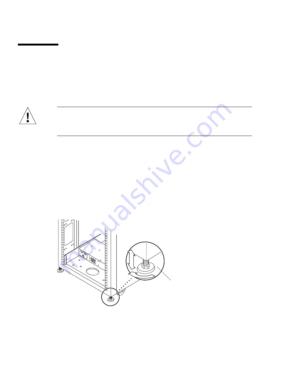
Leveling pads (screws) are located at each corner of the base of the expansion
cabinet (

FIGURE 1-1

).

Caution –

If you will not be using the four floor mounting brackets, the four

leveling pads mounted on the bottom plate of the rack must be lowered to the floor
for the expansion cabinet to meet Underwriters’ Laboratories physical stability
requirements.

1. Open the rear door.

2. Remove the leveling wrench by unlocking the plastic strap that holds it to the

inside of the frame, near the top of the expansion cabinet.

Do not cut the strap. Press the plastic tab to unlock the strap around the wrench,
then slide part of the strap through the lock to loosen the wrench.

3. Adjust the four leveling pads on the expansion cabinet frame using the leveling

wrench.

The four pads should press against the floor so that the expansion cabinet does not
move or rock in any direction.

FIGURE 1-1

Leveling Pad

Proceed to the next section.

Leveling
pad

Summary of Contents for StorEdge

Page 1: ...01 San Antonio Road Palo Alto CA 94303 4900 U S A 650 960 1300 Send comments about this document to docfeedback sun com Sun StorEdge Expansion Cabinet Installation and Service Manual Part No 805 3067 14 July 2000 Revision A ...

Page 2: ...Sun Microsystems Inc 901 San Antonio Road Palo Alto CA 94303 4900 Etats Unis Tous droits réservés Ce produit ou document est protégé par un copyright et distribué avec des licences qui en restreignent l utilisation la copie la distribution et la décompilation Aucune partie de ce produit ou document ne peut être reproduite sous aucune forme par quelque moyen que ce soit sans l autorisation préalabl...

Page 3: ...ipment Sun Microsystems is not responsible for regulatory compliance of a modified Sun product Placement of a Sun Product Caution Do not block or cover the openings of your Sun product Never place a Sun product near a radiator or heat register Failure to follow these guidelines can cause overheating and affect the reliability of your Sun product SELV Compliance Safety status of I O connections com...

Page 4: ...gen befolgen um Stromschläge und Verletzungen zu vermeiden Ein Setzt das System unter Wechselstrom Je nach Netzschaltertyp an Ihrem Gerät kann eines der folgenden Symbole benutzt werden Aus Unterbricht die Wechselstromzufuhr zum Gerät Wartezustand Stand by Position Der Ein Wartezustand Schalter steht auf Wartezustand Änderungen an Sun Geräten Nehmen Sie keine mechanischen oder elektrischen Änderun...

Page 5: ...produire un court circuit qui entraînerait des flammes des risques d électrocution ou des dégâts matériels Symboles Vous trouverez ci dessous la signification des différents symboles utilisés Attention risques de blessures corporelles et de dégâts matériels Veuillez suivre les instructions Attention surface à température élevée Evitez le contact La température des surfaces est élevée et leur conta...

Page 6: ...icrosystems Precauciones de seguridad Para su protección observe las siguientes medidas de seguridad cuando manipule su equipo Siga todas los avisos e instrucciones marcados en el equipo Asegúrese de que el voltaje y la frecuencia de la red eléctrica concuerdan con las descritas en las etiquetas de especificaciones eléctricas del equipo No introduzca nunca objetos de ningún tipo a través de los or...

Page 7: ...iesgo de descargas eléctricas conéctelo siempre a un enchufe con toma de tierra La siguiente advertencia se aplica solamente a equipos con un interruptor de encendido que tenga una posición En espera Precaución El interruptor de encendido de este producto funciona exclusivamente como un dispositivo de puesta en espera El enchufe de la fuente de alimentación está diseñado para ser el elemento prima...

Page 8: ...viii Sun StorEdge Expansion Cabinet Installation and Service Manual July 2000 GOST R Certification Mark ...

Page 9: ... Stabilizer Legs 1 5 1 6 Installing the Floor Brackets 1 7 2 Cabling the Expansion Cabinet 2 1 2 1 Preparing the Expansion Cabinet 2 1 2 2 Connecting the AC Power Cord 2 3 2 3 Connecting the Ground Strap 2 6 2 4 Final Cabling Tasks 2 8 3 Powering On and Off 3 1 3 1 Powering On the Expansion Cabinet 3 1 3 2 Powering Off the Expansion Cabinet 3 4 4 Installing and Removing Devices 4 1 4 1 Rackmount P...

Page 10: ...2 Replacing the Side Panel 4 8 4 6 Troubleshooting the Cabinet 4 8 5 Cabinet Subassemblies 5 1 5 1 Tools Required 5 1 5 2 Key Switch 5 2 5 3 AC Input Cable Assembly 5 4 5 4 Power Sequencer 5 6 A Product Specifications A 1 A 1 Physical Characteristics A 1 A 2 Physical Specifications A 2 A 3 Clearance and Service Access A 2 A 4 Electrical Specifications A 3 A 5 Environmental Requirements A 3 A 6 Ope...

Page 11: ...ot cover the installation procedures for storage devices To install storage devices in the expansion cabinet refer to the documentation shipped with the storage device Using UNIX Commands This document does not contain information on basic UNIX commands and procedures such as shutting down the system booting the system and configuring devices See one or more of the following for this information S...

Page 12: ...You have mail AaBbCc123 What you type when contrasted with on screen computer output su Password AaBbCc123 Book titles new words or terms words to be emphasized Command line variable replace with a real name or value Read Chapter 6 in the User s Guide These are called class options You must be superuser to do this To delete a file type rm filename TABLE P 2 Shell Prompts Shell Prompt C shell machi...

Page 13: ...tation from Sun Microsystems Inc For a list of documents and how to order them visit the Sun Documentation Center on Fatbrain com at http www fatbrain com documentation sun TABLE P 3 Related Documentation Title Part Number Sun StorEdge A3500 Hardware Configuration Guide 805 4981 Sun StorEdge A5000 Tasks and Documentation Guide 805 1903 Sun StorEdge D1000 and A1000 Rackmount Installation Guide 805 ...

Page 14: ...000 Sun Welcomes Your Comments Sun is interested in improving its documentation and welcomes your comments and suggestions You can email your comments to Sun at docfeedback sun com Please include the part number 805 3067 14 of your document in the subject line of your email ...

Page 15: ...assemblies Four floor mounting brackets Two stabilizer legs Associated mounting hardware The floor mounting brackets enable you to bolt the expansion cabinet to the floor If you will not be installing the floor mounting brackets you should install the stabilizer legs The stabilizer legs are extended to prevent the expansion cabinet from tipping over when devices are installed removed or serviced ...

Page 16: ...re shipped with the unit A typical expansion cabinet can weigh from 500 to 1100 pounds 226 kg to 499 kg 2 Unpack the expansion cabinet Refer to the unpacking instructions printed on the shipping carton Note The stabilizer legs floor mounting brackets and associated hardware are packed in the side saddles of the packing material that encase the expansion cabinet 3 Verify that the components you rec...

Page 17: ... Appendix A Product Specifications when you are determining where to place the expansion cabinet Caution Never lift the expansion cabinet by the cosmetic panel surfaces or pull by the rear door Use three or more people to move the expansion cabinet safely Two people must restrain the front of the expansion cabinet to control the movement One person should be behind the expansion cabinet To prevent...

Page 18: ...loor for the expansion cabinet to meet Underwriters Laboratories physical stability requirements 1 Open the rear door 2 Remove the leveling wrench by unlocking the plastic strap that holds it to the inside of the frame near the top of the expansion cabinet Do not cut the strap Press the plastic tab to unlock the strap around the wrench then slide part of the strap through the lock to loosen the wr...

Page 19: ...pansion cabinet from tipping over when devices are taken out of the expansion cabinet The stabilizer legs must be properly installed and set to be effective Caution Always extend the stabilizer legs before you attempt to install new devices or service devices in the expansion cabinet 1 Loosen the securing screw on the right stabilizer leg FIGURE 1 2 FIGURE 1 2 Stabilizer Legs Right stabilizer leg ...

Page 20: ...t Stabilizer Leg 3 Tighten the securing screw This prevents the stabilizer leg from falling off the mounting screws when it is extended 4 Fully extend the right stabilizer leg 5 Repeat Step 1 through Step 4 for the left stabilizer leg 6 Use the leveling wrench and adjust the feet on both stabilizer legs so that they touch the ground FIGURE 1 4 FIGURE 1 4 Adjusting The Leveling Pads on the Stabiliz...

Page 21: ...e used in place of the stabilizer legs when you want to attach the expansion cabinet to the floor Caution Do not bolt the floor mounting brackets to the deck plating of a raised computer floor Note If you are installing the floor brackets over previously installed threaded rods you should loosely install the floor brackets to the rods and then to the expansion cabinet 1 Remove the three mounting s...

Page 22: ...h the right floor brackets to the front and back of the expansion cabinet FIGURE 1 6 FIGURE 1 6 Attaching the Floor Brackets 3 Bolt the right floor brackets to the floor The bolts to secure the floor brackets to the floor are not included 4 Repeat Step 1 through Step 3 for the left floor brackets Floor bracket ...

Page 23: ...inets For instructions on how to cable storage device options in the cabinet see the documentation that is shipped with each device 2 1 Preparing the Expansion Cabinet 1 Verify that the key switch located at the bottom front of the expansion cabinet is in the Standby position FIGURE 2 1 Keys for this switch are packed in the kit that was shipped with your cabinet FIGURE 2 1 Location of Key Switch ...

Page 24: ...n and Service Manual July 2000 2 Open the rear door of the expansion cabinet FIGURE 2 2 FIGURE 2 2 Opening the Rear Door of the Expansion Cabinet 3 Loosen the four screws on the front and rear trim panels and remove the panels Set the panels aside ...

Page 25: ...any other type of power system 1 Open the rear door FIGURE 2 2 2 Verify that each AC power sequencer circuit breaker is in the Off position and the Local Remote switch is in the Local position FIGURE 2 3 FIGURE 2 3 Power Sequencer Control Panel SWITCHED OUTLET CONTROL M A I N P O W E R POWER AVAILABLE SWITCHED OUTLETS LOCAL REMOTE J15 OUT OFF J14 IN AC power sequencer circuit breaker Power Off Pow...

Page 26: ...d to the power sequencer connectors FIGURE 2 4 Flip the cover latch open to access the connectors TABLE 2 1 Voltage Requirements for Maximum Operating Voltage and Frequency Ranges AC voltage rating 200 to 240 VAC AC voltage range 180 to 264 VAC Frequency range 47 to 63 Hz TABLE 2 2 Current Requirements at Nominal Line Voltage for a Cabinet in Maximum Configuration Nominal AC input voltage rating s...

Page 27: ...ower cord directly through the opening in the cabinet base 6 Connect the other end of the AC power cord to a grounded outlet The following connector types are provided on the power cord NEMA L6 30P for 200 240V North American operation 32A single phase IEC 309 connector for 220 240V international operation Caution Risk of electric shock Do NOT turn on AC power to the unit yet ...

Page 28: ... the Ground Strap Caution The installer must install an insulated grounding conductor as part of the circuit supplying power to the unit or system This conductor must be of identical size insulation material and thickness to the neutral grounded and hot ungrounded branch circuit supply conductors but green with or without yellow stripe s The grounding conductor described in the above caution state...

Page 29: ... power sequencer on the system cabinet or cabinet nearest to the expansion cabinet FIGURE 2 5 FIGURE 2 5 Connecting the Ground Strap to the System Cabinet Power Sequencer 3 Screw the other end of the ground strap the front power sequencer in the expansion cabinet FIGURE 2 6 Ground strap ...

Page 30: ...lace the trim panels Tighten the two screws to secure the front and rear trim panels to the cabinet Note Cables should be routed between the bottom panel and the kick panel if you are routing cables under the floor 2 Close the rear door For pre configured expansion cabinets go to Chapter 3 If you are installing a device in the expansion cabinet go to Chapter 4 Ground strap ...

Page 31: ...To avoid damage to internal circuits do not connect or disconnect any cable while the system is powered on 3 1 Powering On the Expansion Cabinet 1 Verify that the key switch located at the bottom front of the expansion cabinet is in the Standby position FIGURE 3 1 FIGURE 3 1 Location of Key Switch on Bottom Front Panel Key switch ...

Page 32: ...n provides a ground path that prevents damage from electrostatic discharge Caution Never move the system or expansion cabinets when system power is on Excessive movement can cause catastrophic disk drive failure Always power the system off before moving it 4 Set the Local Remote switch on the expansion cabinet to Local FIGURE 3 2 5 Turn the AC power sequencer circuit breakers on the expansion cabi...

Page 33: ...ck the status of the rear power sequencer open the rear door of the expansion cabinet and look at the three green LEDs on the rear power sequencer 7 Turn the power on to the system cabinet See the installation manual you received with your system cabinet for instructions You may have to enter a specific software command when booting the system so that the system will recognize the expansion cabine...

Page 34: ...ilure to stop I O between host system s and devices in the expansion cabinet can result in the loss of data 1 Stop I O to devices in the expansion cabinet 2 Turn the key switch located at the front of the cabinet to the Standby position FIGURE 3 1 3 At the bottom of the expansion cabinet remove the trim panels and turn the AC power sequencer circuit breakers to Off FIGURE 3 2 4 If you are servicin...

Page 35: ...move systems from top to bottom to prevent raising the center of gravity of the rack Use extra caution when moving the rack onto ramps 4 1 Rackmount Placement Rackmount placement information for devices that can be mounted in Sun system and expansion cabinets is now available through the Web at http docs sun com Click on Storage and Peripherals in the Hardware section and open the Rackmount Placem...

Page 36: ...ant to be used in conjunction with those that shipped with the device you are installing Read both procedures before beginning the installation Note You may need to remove the side panels from the cabinet If so also perform the steps in Section 4 5 Side Panel Removal and Replacement on page 4 7 1 Determine where you are going to install the device Refer to the online Rackmount Placement Matrix 2 O...

Page 37: ...intain proper airflow filler panels must be installed over locations that do not have devices mounted FIGURE 4 1 Filler Panel and Trim Strip Installation 5 If the expansion cabinet is not bolted to the ground extend the stabilizer legs The stabilizer legs are located under the front of the cabinet Caution Only extend or retract the stabilizer legs as a pair Be sure that the levelers have been adju...

Page 38: ...rdered without any devices installed has the power cables routed as shown in FIGURE 4 2 FIGURE 4 2 Power Cable Routing Caution Power cable routing can vary depending on how the expansion cabinet is configured in the factory for instance the power cabling in a StorEdge A3500 1x8 expansion cabinet is different than that in a expansion cabinet configured with StorEdge A5000 disk arrays Refer to the d...

Page 39: ...pin with the outside hole of the top left mounting bracket d Release the lever The hinge pin will extend into the mounting bracket 4 4 Removing a Device These instructions are meant to be used in conjunction with those that shipped with the device you are installing Read both procedures before beginning the installation Note If you are told to remove the side panels in the instructions that came w...

Page 40: ...ine Rackmount Placement Matrix and the documentation that came with your device 5 If you will not be reinstalling the device install a filler panel over its previous location FIGURE 4 1 Use a Phillips screwdriver to tighten the captive screws Note To maintain proper airflow filler panels must be installed over locations that do not have devices mounted 6 If necessary retract the stabilizers under ...

Page 41: ...anel Removal and Replacement 4 5 1 Removing the Side Panel Use an Allen wrench to loosen the four 1 4 inch shoulder screws that fasten the panel to the cabinet and remove the panel from the cabinet FIGURE 4 3 FIGURE 4 3 Removing and Replacing the Side Panels ...

Page 42: ...oting the Cabinet Use this checklist as a guide for isolating common installation problems 1 Verify that all terminators are properly installed 2 Verify that all power and data cables are properly installed 3 Verify that the same SCSI address is not being used by two or more drives on the same SCSI bus 4 Verify that the power is turned on to the drives trays and cabinet See the service manual for ...

Page 43: ...s the procedures for removal and replacement of all field replaceable units FRUs for the expansion cabinet 5 1 Tools Required Screwdriver Phillips 2 Screwdriver slotted 1 4 inch Needlenose pliers Note For expansion cabinet access information see Chapter 4 ...

Page 44: ...nect the key switch cable connector from the cable adapter cable connector near the rear of the power sequencers FIGURE 5 1 The adapter cable remains connected to the power sequencer FIGURE 5 1 Key Switch Cable Connection 3 Remove the Phillips screws and cable ties that secure the key switch cable to the chassis frame Each screw secures a clamp on the frame that holds the cable in place Key switch...

Page 45: ... switch into the panel opening 2 Facing the back of the key switch on the inside of the cabinet slide the metal clip onto the notch of the key switch body to secure it in place FIGURE 5 2 3 Route the key switch cable to the power sequencer securing it to the chassis frame with cable ties and Phillips screws Each screw secures a clamp on the frame that holds the cable in place 4 Connect the key swi...

Page 46: ...ssembly Caution Be sure that the power to the expansion cabinet is completely turned off See Chapter 3 Powering Off the System 1 Disconnect the AC power cord from the power connector on the power sequencer FIGURE 5 3 2 Close the power connector cover 3 Pull the latch up over the cover to secure it FIGURE 5 3 Removing the AC Input Cable ...

Page 47: ...nsion cabinet is completely turned off See Chapter 3 1 Pull back the power connector cover FIGURE 5 3 Flip the cover latch open to access the connector 2 Connect the power cord to the power connector 3 Pull the latch over the power cord to secure it to the power connector 4 Power on the expansion cabinet See Chapter 3 ...

Page 48: ...4 2 Disconnect the key switch adapter cable from the mating power supply connector at the rear of the power sequencer FIGURE 5 4 FIGURE 5 4 Power Sequencer 3 Remove the AC power cord from the power sequencer See Section 5 3 AC Input Cable Assembly on page 5 4 4 Remove the screws that secure the sequencer to the chassis 5 Slide out the power sequencer to access the power cables 6 Disconnect all oth...

Page 49: ...2 Connect all cables on the back of the power sequencer 3 Slide the power sequencer into the expansion cabinet FIGURE 5 4 4 Tighten the screws that secure the sequencer to the chassis 5 Connect the AC power cord See Section 5 3 AC Input Cable Assembly on page 5 4 6 Power on the expansion cabinet See Chapter 3 ...

Page 50: ...5 8 Sun StorEdge Expansion Cabinet Installation and Service Manual July 2000 ...

Page 51: ...ack opening is 17 875 inches 454 mm A vertical panel opening of 36 Rack Unit RU minimum is provided to accommodate various rack mountable subsystems One RU is equal to 1 75 inches 44 45 mm Overall cabinet height with cosmetic panels is 73 5 inches 187 cm maximum Cabinet structure and casters are designed to handle a 1300 pounds 589 kg static load Caution Make no mechanical or electrical modificati...

Page 52: ...ABLE A 2 Clearance and Service Access With Service Access Without Service Access Front 48 inches 122 cm 24 inches 61 cm Rear 36 inches 92 cm 24 inches 61 cm Left 36 inches1 92 cm 2 inches2 51 cm Right 36 inches1 92 cm 0 1 Side access may be required for some service procedures Refer to the documentation that came with the devices 2 Sun StorEdge A5000 disk arrays Sun Enterprise 4x00 servers and som...

Page 53: ...nge 47 to 63 Hz Current at 240 VAC 24A Power consumption maximum 5 4 kW TABLE A 4 Operating Environment Parameter Value Temperature Operating 5 C to 35 C 41 F to 95 F Non operating 40 C to 66 C 40 F to 150 8 F Humidity Operating 20 to 80 RH noncondensing 27 C 80 6 F maximum wet bulb Non operating 5 to 95 RH noncondensing Altitude Operating 0 to 9 843 feet 0 to 3 km Non operating 0 to 39 370 feet 0...

Page 54: ...ions described in TABLE A 4 The expansion cabinet should be in a computer room environment Computer room installation provides secure access to computers and stored information and provides control over environmental factors such as temperature humidity and airborne dust Computer room installation can also help protect equipment from fire flood or other danger originating in the building ...

Page 55: ... Parts Part Number Power sequencer universal rack 300 1393 Assembly cable rack AC input international 530 2675 Assembly cable rack AC input domestic 530 2674 Assembly cable universal power cord 530 2197 Assembly cable main rack to expansion interface 530 2236 Key switch panel assembly 540 3804 Filler panel and trim strip kit 595 4853 Note The suffix xx denotes the revision level of an assembly ...

Page 56: ...B 2 Sun StorEdge Expansion Cabinet Installation and Service Manual July 2000 ...

Reviews: