


Installing Four 256 Mbyte Memory Boards
9
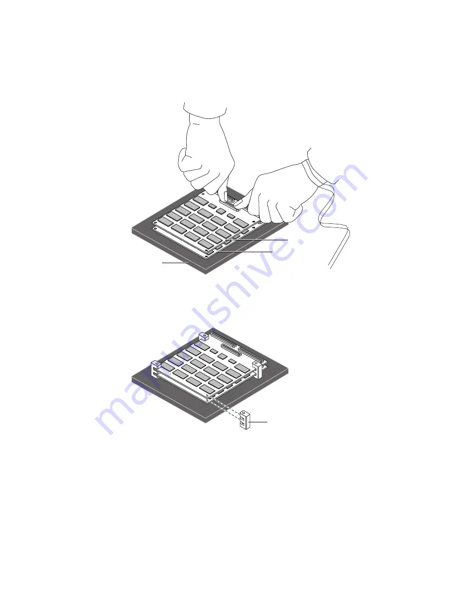
FIGURE 8
Stacking the Third Memory Board on Top of the Second
10. Insert the four plastic spacers and align them with the mounting holes on memory
Boards B and C (see
FIGURE 9
).
FIGURE 9
Aligning the Four Plastic Spacers with the Mounting Holes
Board B
ESD foam
Board C
Spacers


