background image

28

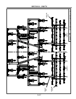
' H

A

R

R

O

W

 L

A

Y

O

U

T

8/

30

/2

01

2

9C

C

28

12

H

.ia

m

/

0"

31

"

54

 1

/4

"

12

1/

4"

13

1/

4"

31

"

54

 1

/4

"

12

1/

4"

13

1/

4"

8H

23

14

(5

2"

)

8H

D

50

98

E

X

T

8H

D

50

98

EX

T

6-40

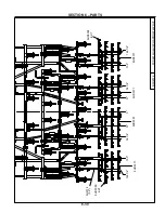
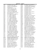
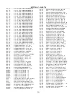
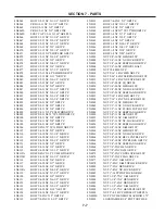
SECTION 6 – PARTS

Summary of Contents for CoulterChisel CC2815

Page 1: ...CTURING CO INC WEB SITE www summersmfg com DEVILS LAKE NORTH DAKOTA 58301 701 662 5391 8Z1095 Summers Mfg Co Inc 2017 Printed in USA IMPORTANT THE OPERATOR IS RESPONSIBLE FORADJUSTING THE MACHINE SINCE MACHINE DOES NOT COME FIELD READY FROM FACTORY COULTER CHISEL DISK CHISEL COULTER CHISEL DISK CHISEL CAUTION READ UNDERSTAND OPERATOR S MANUAL BEFORE USING MACHINE 2009 and newer ...

Page 2: ... the contract of sale or independently thereof and whether or not such claim is based on contract tort or warranty Written permission for any warranty claim return must be first obtained from authorized Summers personnel All returns must be accompanied with a complete written explanation of claimed defects and the circumstances of operational failure Written warranty for all component parts used i...

Page 3: ... B It is the policy of this company in improve its products whenever possible and practical to do so We reserve the right to make changes or improvements in the design or construction of parts at any time without incurring obligations to install such changes on products previously delivered C Reference to right and left in this manual is determined when machine is viewed from the rear D Parts are ...

Page 4: ...s and Coulter Gangs 2 52 2 72 Gang Assembly 2 53 Blade Assembly 2 71 Decals Options 2 72 SECTION 3 OPERATION Operation Safety 3 1 Steps Prior to Operation 3 1 Initial Hookup 3 2 3 5 Field Operation 3 6 3 11 Transporting 3 11 3 12 Unhooking From Tractor 3 12 SECTION 4 MAINTENANCE Maintenance Safety 4 1 Maintenance for after the First Day and Week of Operation 4 1 Daily Maintenance 4 2 Periodic Main...

Page 5: ...enter w Hitch and Locks 6 20 32 40 Wing Assembly 6 21 Gauge Wheel Assembly 6 22 32 40 Transport 6 23 6 24 32 40 Wing Lift Hydraulics 6 25 Safety Light Kit 6 26 Trip Assembly 6 27 Coulter Gang Components 6 28 Coulter Gang Mount Components 6 29 Disk Blade Assembly 6 30 Rear Hitch 6 31 Hub and Axle Components 6 32 614 Hub and GBGI Seal 6 33 Mounted Harrow Mounting Arm Assembly 6 34 Mounted Harrow Ass...

Page 6: ...NOTES iv ...

Page 7: ...st unsafe practices GENERAL SAFETY PRACTICES 1 READ AND UNDERSTAND Operator s Manual before using machine Review at least annually thereafter 2 VERIFY all safety devices and shields are in place before using machine 3 KEEP hands feet hair and clothing away from moving parts 4 STOP engine place all controls in neutral set parking brake remove ignition key and wait for all moving parts to stop befor...

Page 8: ...when transporting on public roads 4 FOLLOW ALL local laws governing transporting of farm machinery 5 Frequently check for traffic from rear especially during turns SAFETY DECALS 1 KEEP SAFETY DECALS CLEAN 2 REPLACE missing or unreadable decals New decals are available from your Summers dealer by ordering correct part number PN located on the decal DECALS AND THEIR LOCATIONS 1 PN 8Z0075 DECAL FOR R...

Page 9: ... SECTION 1 SAFETY 3 PN 8Z0202 DECAL FOR COMPANY IDENTIFICATION 4 PN 8Z0276 DECAL FOR GENERAL CAUTION 5 PN 8Z0340 DECAL FOR REPHASING CYLINDERS 1 3 ...

Page 10: ...TALLING CYLINDER LOCKS 7 PN 8Z0344 DECAL FOR STAYING CLEAR OF WINGS 8 PN 8Z0346 DECAL FOR ELECTROCUTION DANGER 9 PN 8Z0348 DECAL FOR GAUGE WHEEL DEPTH 10 PN 8Z0800 AMBER REFLECTOR 11 PN 8Z0805 RED ORANGE REFLECTOR 12 PN 8Z0810 RED REFLECTOR 1 4 ...

Page 11: ...p 8K8067 when not attached to towing vehicle On most towing vehicles WITHOUT brake lights Amber lights will turn on with flashers or turn signals Red lights will turn on with parking road or field lights On most towing vehicles WITH brake lights Amber lights will turn on with flashers turn signals OR when brake is applied Red lights will turn on with parking or road lights The Summers Safety Light...

Page 12: ...10 8Z0344 8Z0805 8Z0342 8Z0342 8Z0805 8Z0344 8Z0810 8Z0101 8Z0204 8Z0202 8Z0204 8Z0346 8Z0276 8Z0344 8Z0087 8Z2370 16 20 COULTERCHISEL 8Z2375 24 28 COULTERCHISEL 8Z2380 32 40 COULTERCHISEL 8Z2350 16 20 DISKCHISEL 8Z2355 24 28 DISKCHISEL 8Z2360 32 40 DISKCHISEL SECTION 1 SAFETY 1 6 ...

Page 13: ... is a MINIMUM OF 22 WIDE Height requirement varies up to 16 3 Shanks may be left off to reduce height and width requirement 4 Reference to RIGHT and LEFT is determined when machine IS VIEWED FROM THE REAR 5 Reference to FORWARD means TOWARDS THE TRACTOR 6 Reference to REAR means AWAY FROM THE TRACTOR SAFETY ALERT SYMBOL This symbol is an alert to the potential for personal injury This symbol means...

Page 14: ... may impair the function and or safety of the machine USE SUITABLE LIFTING DEVICE for components which could cause personal injury BLOCK UPANY RAISED PART ofthemachine Besuremachine is stable after blocking ALWAYS INSPECT LIFTING CHAINS AND SLINGS for damage or wear BE SURE LIFTING DEVICE IS RATED TO HANDLE THE WEIGHT STOP ENGINE place all con trols in neutral set parking brakes remove ignition ke...

Page 15: ... 16 20 CENTER 8CC5230 8X0260 3 4 N 8X0306 3 4 LW 8K5515 3 4 X 4 X 6 SECTION 2 SET UP OF 16 20 DISK CHISEL COULTER CHISEL MAIN FRAME 1 Place front center and rear sections on floor with bolt plates facing each other 2 ATTACH sections with 48 3 4x2 1 4 bolts lock washers and nuts as shown 3 Block center frames off the floor 2 3 ...

Page 16: ...th lock nut Install 8T4190 left and 8T4192 right mud guards as shown Secure with 3 8 u bolts and flange nuts 8 Hang cylinders in correct locations Use 6 x 10 8T1060 on left hand side 5 5 x 10 8T1055 on right hand side 9 Install 8K1100 axle and hub assembly into each walking tandem Apply good quality anti seize to axles before installation Retain axle into receiver tube with 1 2 x 3 3 4 bolt and lo...

Page 17: ... 8X0044 7 16 X 3 1 2 8K1640 8CC4010 8X0285 1 1 2 N 8T2040 8T4224 8K1683 8X0285 1 1 2 N 8K5515 3 4 X 4 X 6 8X0306 3 4 LW 8X0260 3 4 N 8X0120 3 4 X 9 6 2 6 2 8X0246 1 2 FN 8X0203 3 8 FN 8CC0805 8X0001 3 8 X 3 4 8X0077 1 2 X 7 1 2 8CC0800 8P7250 2 5 SECTION 2 SET UP OF 16 20 DISK CHISEL COULTER CHISEL MAIN FRAME ...

Page 18: ...660 8X0044 7 16 X 3 1 2 8K5515 3 4 X 4 X 6 8X0306 3 4 LW 8X0260 3 4 N 8K1100 8X0072 1 2 X 3 3 4 8X0234 7 16 LNUT 8X0044 7 16 X 3 1 2 8X0234 7 16 LNUT 8T3620 8X0203 3 8 FN 8T4190 8A1156 3 8 X 4 1 16 X 5 8K7033 8R6914 8X0234 7 16 LNUT 8X0044 7 16 X 3 1 2 8T3640 8T4100 8CC4140 8T4166 LEFT 8T4168 RIGHT LEFT 8T4192 RIGHT SECTION 2 SET UP OF 16 20 DISK CHISEL COULTER CHISEL MAIN FRAME 2 6 ...

Page 19: ...C1310 20 SHOWN 8CC1300 16 AS REQUIRED 8D9108 1 4 X 2 RP 8K9102 8X0306 3 4 LW 8X0260 3 4 N 8K5515 3 4 X 4 X 6 8X0368 1 1 2 FW 8X0234 7 16 LNUT 8X0044 7 16 X 3 1 2 8K1660 8K8435 SECTION 2 SET UP OF 16 20 DISK CHISEL COULTER CHISEL MAIN FRAME 2 7 ...

Page 20: ...0 8X0260 3 4 N 8X0306 3 4 LW 8K5515 3 4 X 4 X 6 SECTION 2 SET UP OF 24 28 DISK CHISEL COULTER CHISEL MAIN FRAME 1 Place front center and rear sections on floor with bolt plates facing each other 2 ATTACH sections with 48 3 4x2 1 4 bolts lock washers and nuts as shown 3 Block center frames off the floor 2 8 ...

Page 21: ...ecure with lock nut Install 8T4190 left and 8T4192 right mud guards as shown Secure with 3 8 u bolts and flange nuts 8 Hang cylinders in correct locations Use 5 5 x 10 8T1055 on left hand side 5 0 x 10 8T1050 on right hand side 9 Install 8K1100 axle and hub assembly into each walking tandem Apply good quality anti seize to axles before installation Retain axle into receiver tube with 1 2 x 3 3 4 b...

Page 22: ... W CYL ATTCH 8 6 2014 9CC2412H iam q 8T4224 8K5515 3 4 X 4 1 16 X 6 8X0306 3 4 LW 8X0260 3 4 N 8K1683 8X0285 1 1 2 N 8X0285 1 1 2 N 6 6 6 6 SECTION 2 SET UP OF 24 28 DISK CHISEL COULTER CHISEL MAIN FRAME 2 10 ...

Page 23: ...7 16 LNUT 8X0044 7 16 X 3 1 2 8T3620 8K9106 8D9108 1 4 X 2 RP 8T1055 8T1050 8CC4325 8K5515 3 4 X 4 X 6 8X0306 3 4 LW 8X0260 3 4 N 8T4100 8K5515 3 4 X 4 X 6 8X0306 3 4 LW 8X0260 3 4 N 8X0044 7 16 X 3 1 2 8X0234 7 16 LNUT 8T3640 8T3300 8L0252 8T3800 8L0252 8X0316 1 FW 8X0282 8D9524 8T4166 8CC4140 8CC4140 SECTION 2 SET UP OF 24 28 DISK CHISEL COULTER CHISEL MAIN FRAME 2 11 ...

Page 24: ...0223 1 4 FN 8K8067 8X0000 1 4 X 3 4 8S1126 8S1120 8A1156 3 8 X 4 1 16 X 5 8T2040 8P7250 8X0285 1 1 2 N 8T4350 8X0402 8X0440 8T4380 8X0240 1 2 N 8X0303 1 2 LW 8X0234 7 16 LNUT 8K1640 8X0044 7 16 X 3 1 2 8CC4012 8X0260 3 4 N 8X0306 3 4 LW 8X0120 3 4 X 9 8S0340 1 2 X 4 X 5 1 4 SQ 8CC4010 8D8522 8CC4000 8CC0600 SECTION 2 SET UP OF 24 28 DISK CHISEL COULTER CHISEL MAIN FRAME 2 12 ...

Page 25: ...der with 3 4 x 1 1 4 bolt and flat washer 18 Attach hitch jack to jack spool 19 Remove blocks from under center frame and allow wheel assemblies to support machine Block tires to prevent movement 20 Add depth control cylinder locks and storage bases 21 Install SMV sign mounting bracket and sign at center of rear rank 22 Install Disk Mounting Tube as shown on page 2 18 ...

Page 26: ...s Washers are used to center wing in hinges and prevent shift 2 Fasten cylinder attach brackets with 3 4 u bolts located 126 1 2 from machine center 3 Insert eyebolts 8K1683 into cylinder attach bracket Tighten 1 1 2 nuts so the same amount of threads are above top nut on all eyebolts Insure that cylinder attach holes are aligned when eyebolts are tightened 4 Center liftarm under cylinder attach b...

Page 27: ...7 16 LNUT 8T3620 8X0044 7 16 X 3 1 2 8CC4140 8T4168 8T3640 8K5515 3 4 X 4 X 6 8X0234 7 16 LNUT 8X0044 7 16 X 3 1 2 8X0306 3 4 LW 8X0260 3 4 N 8T4100 8K1100 8K7033 8R6914 8X0077 1 2 X 7 1 2 8T4174 8S0660 8X0242 NY LOCK 1 2 N 8X0074 1 2 X 4 1 2 8T4179 8K9106 8D9108 1 4 X 2 RP 8T1060 SECTION 2 SET UP OF 24 28 DISK CHISEL COULTER CHISEL WINGS 2 15 ...

Page 28: ... wing 7 Install 8K1100 axle and hub assembly into each walking tandem Apply good quality anti seize to axles before installation Retain axle into receiver tube with 1 2 x 3 3 4 bolt and locknut 8 Attach wheels onto hubs with 9 16 wheel bolts torque required 170 ft lbs 9 26 28 Only Install wing extensions One shank extension must be placed on rear rank Two shank extension must be placed on front tw...

Page 29: ...WING EXT 7 13 2012 9DC2812H iam 28 ONLY 26 28 ONLY 8T4060 8X0260 3 4 N 8X0306 3 4 LW 8X0112 3 4X2 1 4 8CC4075 SECTION 2 SET UP OF 24 28 DISK CHISEL COULTER CHISEL WINGS 2 17 ...

Page 30: ...1 2 8K1660 8X0368 1 1 2 FW 8K5515 3 4 X 4 X 6 8X0306 3 4 LW 8X0260 3 4 N 8CC1005 8K9102 8D9108 1 4 X 2 RP 8K8435 8K8430 8CC1320 8CC1330 24 LEFT SHOWN 8CC1340 24 RIGHT 8CC1350 26 28 LEFT 8CC1360 26 28 RIGHT SECTION 2 SET UP OF 24 28 DISK CHISEL COULTER CHISEL GANG TUBE 2 18 ...

Page 31: ...N 8CC5210 8T4030 SECTION 2 SET UP OF DISK CHISEL COULTER CHISEL CENTER SECTION 32 40 2 19 1 Place front center and rear sections on floor with bolt plates facing each other 2 ATTACH sections with 48 3 4x2 1 4 bolts lock washers and nuts as shown 3 Block center frames off the floor ...

Page 32: ...s as shown Secure with 3 8 u bolts and flange nuts 7a Install front caster attach assemblies Install 8CC6010 hitch towers onto frame with 1 1 2 bolts 4 with lockwashers and nuts Do not tighten nuts until after caster beam 8CC6000B is installed Attach top of 8CC6015 braces to hitch towers with 7 8 x 2 bolts and lockwashers nuts are attached inside hitch tower Use 7 8 x 2 1 2 bolts with lockwashers ...

Page 33: ...5 X 9 8X0315 1 1 2 LW 8X0285 1 1 2 N 8CC6010 8X0268 7 8 N 8X0307 7 8 LW 8X0132 7 8 X 2 1 2 8CC6015 8X0130 7 8 X 2 8X0307 7 8 LW 8X0260 3 4 N 8X0306 3 4 LW 8X0318 3 4 FW 8X0111 3 4 X 2 1 2 8X0318 3 4 FW 8X0306 3 4 LW 8X0111 3 4 X 2 1 2 8CC6028 8X0285 1 1 2 N 2 21 SECTION 2 SET UP OF DISK CHISEL COULTER CHISEL CENTER SECTION 32 40 ...

Page 34: ... 32 8K9640 SECTION 2 SET UP OF DISK CHISEL COULTER CHISEL CENTER SECTION 32 40 2 22 11 Insert 1 1 2 x 10 3 8 eyebolts into wing lift cylinder attach base Leave 1 1 2 nuts loose they will need to be adjusted after wing is installed 12 Attach wing lift cylinders to frame with pins and roll pins 32 machine uses 4 x 36 cylinders 8K9640 36 40 machines use 5 x 36 cylinders 8K9650 ...

Page 35: ...ion with pins washers bolts and locknuts Washers are used to center wing in hinges and prevent shift 2 Fasten cylinder attach brackets with 3 4 u bolts located 169 from machine center 3 Insert eyebolts 8K1755 into cylinder attach bracket Tighten 1 1 2 nuts so the same amount of threads are above top nut on all eyebolts Insure that cylinder attach holes are aligned when eyebolts are tightened 4 Cen...

Page 36: ...ion must be placed on rear rank Two shank extension must be placed on front two ranks Mounting bolts must point toward outside of machine Trip assembly interference will occur if this is not followed 10 Install gauge wheel support 8T4090 onto wing with 7 8 x 2 1 2 bolts NOTE Steps 10 through 15 may have been pre assembled at factory 11 Apply anti seize to jack bolt 8T6000 threads Screw jack bolt i...

Page 37: ...16 X 3 1 2 8X0234 7 16 LNUT 8T3620 8T4140 8D0340 3 4 X 4 X 7 3 4 8X0234 7 16 LNUT 8X0260 3 4 N 8X0306 3 4 LW 8K5515 3 4 X 4 X 6 8T4100 8X0044 7 16 X 3 1 2 8T3640 8X0242 NY LOCK 1 2 N 8X0322 1 2 FW 8X0067 1 2 13NCX2 1 4 8X0261 3 4 LN 8T3120 8T4168 LEFT 8T4166 RIGHT 8K1100 8X0242 NY LOCK 1 2 N 8X0072 1 2 X 3 3 4 8X0203 3 8 FN 8T4190 8T4166 8A1156 3 8 X 4 1 16 X 5 LEFT 8T4192 RIGHT LEFT 8T4168 RIGHT ...

Page 38: ... 16 X 3 1 2 8X0234 7 16 LNUT 8T3620 8K5515 3 4 X 4 X 6 8T4100 8X0306 3 4 LW 8X0260 3 4 N 8X0234 7 16 LNUT 8X0044 7 16 X 3 1 2 8T3640 8D0340 3 4 X 4 X 7 3 4 8X0067 1 2 13NCX2 1 4 8X0261 3 4 LN 8X0322 1 2 FW 8X0242 NY LOCK 1 2 N 8T3120 8L1110 8T4168 LEFT 8T4166 RIGHT 8K7037 8K7037 8K1105S 8X0072 1 2 X 3 3 4 8X0242 NY LOCK 1 2 N 8X0203 3 8 FN 8T4190 LEFT 8T4192 RIGHT 8T4166 LEFT 8T4168 RIGHT 8A1156 3...

Page 39: ...amount of threads should ap pear on top and bottom of u bolt 20 Trip assemblies located at 162 will be attached with 3 4 x 6 bolts These bolts will also hold the liftarm pivot bracket at that location 21 Install Disk Mounting Tubes as shown below 22 Attach lower link arms 8CC6026 to hitch towers with 8T3620 pins and retain with 7 16 x 3 1 2 bolts and nylock nuts Bolt the two rockshaft halves toget...

Page 40: ...lockwasher and nut onto bottom of caster arm Install hubs 8K1105S as shown and retain with 1 2 x 3 3 4 bolt and nylock nut Attach wheel and tire assemblies Tighten lug nuts to 240 ft lbs 28 Tighten slotted nut 8X0292 so that caster wheel assembly cannot be moved by human force Retain slotted nut with 3 8 hardware as shown 29 Attach hitch to center with 1 1 2 x 10 5 8 pins NOTE Center with 1 1 2 ID...

Page 41: ...0123A 3 4 X 5 5 8X0259 3 4 JN 7P7289 8P7200 8P7210 8CC6000B 8CC6026 8X0133 7 8 X 3 8X0307 7 8 LW 8X0268 7 8 N 8X0044 7 16 X 3 1 2 8X0234 7 16 LNUT 8T3620 8CC6022 8T3620 8X0044 7 16 X 3 1 2 8X0234 7 16 LNUT 2 29 SECTION 2 SET UP OF 32 40 CASTER WHEELS HITCH ...

Page 42: ...8X0320 3 8 FW 8X0202 3 8 LN 8X0292 2 SLTD N 8K5200 7L2150 8L0320 7P8530 8X0261 3 4 LN 8X0072 1 2 X 3 3 4 8K1105S 8X0284 1 1 4 N 8X0311 1 1 4 LW 8CC6035 8X0113 3 4 X 5 8CC6030B 8K7037 8X0242 NY LOCK 1 2 N SECTION 2 SET UP OF 32 40 CASTER WHEELS HITCH 2 30 ...

Page 43: ...0 3 8 X 8 X 9 8X0203 3 8 FN 8W1398 8X0234 7 16 LNUT 8X0044 7 16 X 3 1 2 8K1640 8CC4000 32 36 8T4000 40 ONLY 8K3002 8CC0600 8T0606 8T0608 NOTE 8K3002 WRENCHES AND 8CC0600 WRENCH HOLDERS USED ON COULTER CHISELS ONLY 8T0606 AND 8T0608 WRENCHES USED ON DISK CHISELS ONLY WRENCH HOLDER STUDS 2 31 SECTION 2 SET UP OF 32 40 CASTER WHEELS HITCH ...

Page 44: ... to support machine Block tires to prevent movement 34 Add depth control cylinder locks and storage bases Attach locks for rear cylinders by liftarm pivots located closest to center of machine Locate lock for front center cylinder on front 4 x 4 tube 35 Install SMV sign mounting bracket and sign at center of rear rank ...

Page 45: ... 8J6020 3 4 16ORB X 10 JIC M 90 ADP 8D3212 3 4 ORB TIP ISO 8J5520 3 4 ORB X 10 STR 8D3212 3 4 ORB TIP ISO 8T1010 POPPET 8T1008 PLASTIC PLUNGER REPAIR KIT 8N6570 3 4 X 570 8N4228 1 2 X 228 8N4546 1 2 X 546 16 20 MACHINES 8T1060 TOP VIEW TO 8T1055 TO TRACTOR 2 33 SECTION 2 HYDRAULIC SET UP 16 20 ...

Page 46: ... DEPTH CONTROL HYDRAULICS 16 20 MACHINES 8C1710 3 8 X 8 X 9 7W1420 8S2990 HOSE CLMP 8X0202 3 8 LN 8K8435 8J6010 3 4 16ORB X 6JIC M 90 ADP 8K8435 8J5300 6 JIC M TEE 8J5700 6 JIC F SW X 6 JIC M 90 ADP 8J5510 3 4 ORB X 6 JIC M 8D3212 3 4 ORB TIP ISO 8N3060 2X 3 8 X 60 2 34 SECTION 2 HYDRAULIC SET UP 16 20 ...

Page 47: ...rs will not operate properly unless they are connected correctly 2 Special attention should be paid to routing of hydraulic hoses Diagram below shows layout of hoses for depth control cylinders A It is best to start by routing the hose for the 6 x 10 cylinder Make sure there is 60 of hose ahead of hose holder This is usually enough hose for safe and easy hook up to tractor B Route hose along hitch...

Page 48: ...before next step 4 Hydraulic hoses and fittings for wing lift cylinders are shown in the following drawing The wing lift hydraulic circuit is equipped with a one way restrictor to prevent free fall of the wings when being lowered Be sure that the restrictor is installed so the arrow points toward the cylinder This will restrict oil flowing out of the cylinder but not flowing in 5 Route hoses along...

Page 49: ...0 JIC M 90 ADP 8T1055 8J6020 3 4 16ORB X 10 JIC M 90 ADP 8T1060 8J5520 3 4 ORB X 10 STR 8J5520 3 4 ORB X 10 STR 24 28 MACHINES TO TRACTOR TO 8T1055 8T1060 TOP VIEW 8T1010 POPPET 8T1008 PLASTIC PLUNGER REPAIR KIT 8D3212 3 4 ORB TIP ISO 8J5510 3 4 ORB X 6 JIC M 8J5520 3 4 ORB X 10 STR 8N6570 3 4 X 570 8N4198 1 2 X 198 8N4228 1 2 X 228 8N4198 1 2 X 198 8N3534 3 8 X 534 SECTION 2 HYDRAULIC SET UP 24 2...

Page 50: ...3028 3 8 X 28 WING LIFT HYDRAULICS 24 28 MACHINE 8D9525 SEAL KIT 5X24 8A1954 1 4 OD TUBE 18 ARROW MUST POINT TOWARD CYLINDER 8J5200 10 F X 6 M BUSH 8J5510 3 4 ORB X 6 JIC M 8J7040 THERMAL RELIEF 8J5680 3 4 X3 4 UNION 8J7116 8J5620 3 4 X 6 JIC F SW 8J5200 10 F X 6 M BUSH 8J6030 7 8 X 10 M 90 ADP 8J6030 7 8 X 10 M 90 ADP 8J5200 10 F X 6 M BUSH 8J5620 3 4 X 6 JIC F SW 8J7116 8J5510 3 4 ORB X 6 JIC M ...

Page 51: ...imes to make sure that all air has been removed from sys tem Leave cylinders in fully extended position 7 Connect rod end of cylinders to wing Follow these steps and see drawing below Use pivot bolt washers with collars 1 1 4 washers 1 washer and 1 lock nut provided 1 1 4 washers must slide freely inside wing flamecuts Do not over tighten lock nut Pivot bolt must rotate freely ...

Page 52: ...0 8 With cylinder attach eyebolts loose raise coulter chisel wings to transport position Fully retract cylinders and let wings rest against transport locks Tighten each eyebolt so pivot bolt and rollers are centered in the wing lift slot ...

Page 53: ...EPTH CONTROL HYDRAULICS 24 28 MACHINE 8K8435 8K8430 8J6010 3 4 16ORB X 6JIC M 90 ADP 8K8435 8J5300 6 JIC M TEE 8J5700 6 JIC F SW X 6 JIC M 90 ADP 8J5510 3 4 ORB X 6 JIC M 8D3212 3 4 ORB TIP ISO NOTE REPHASE CYLINDERS BY FULLY EXTENDING WITH BLADES CONTACTING GROUND 3 5 X 8 MASTER 3 5 X 8 MASTER 3 X 8 SLAVE SECTION 2 HYDRAULIC SET UP 24 28 2 41 ...

Page 54: ...ISO 8J5300 6 JIC M TEE 16 28 COULTER AND DISK CHISEL HYDRAULIC HITCH 8N3048 2X 8X0001 3 8 X 3 4 8X0077 1 2 X 7 1 2 8CC0805 8Z0365 8CC0800 8X0203 3 8 FN 8X0246 1 2 FN 2 42 SECTION 2 HYDRAULIC SET UP 16 28 Hydraulic Hitch Hydraulic Setup 16 28 1 Install Hydraulic hitch hose as shown in the diagram 2 Hydraulic Hitch cylinder should be plumbed in parrallel 3 Route hose along hitch frame 4 Use provided...

Page 55: ... goes to base end of second cylinder and so forth Cylinders will not operate properly unless they are connected correctly 2 Special attention should be paid to routing of hydraulic hoses Diagrahm below shows layout of hoses for depth control cylinders A It is best to start by routing the hose for the 6 x 10 cylinder Make sure there is 60 of hose ahead of hose holder This is usually enough hose for...

Page 56: ...8 8J5100 UNION 8N3018 3 8 X 18 AN ADDITIONAL 8J5100 AND 8N3060 USED ON 40 8N3150 3 8 150 8N6570 3 4 X 570 8J5110 UNION 8N6060 3 4 X 60 8J5110 UNION 8N6060 3 4 X 60 AN ADDITIONAL 8J5110 AND 8N6060 USED ON 40 32 40 DISK COULTER CHISEL CASTER HYD 40 ADDS 8J5110 AND 8N4060 40 ADDS 8J5110 AND 8N4060 8J6020 3 4 16ORB X 10 JIC M 90 ADP 8J6010 3 4 16ORB X 6JIC M 90 ADP 8J6010 3 4 16ORB X 6JIC M 90 ADP TO ...

Page 57: ...aulic hoses and fittings for wing lift cylinders are shown in the following drawing The wing lift hydraulic circuit is equipped with a one way restrictor to prevent free fall of the wings when being lowered Be sure that the restrictor is installed so the arrow points toward the cylinder This will restrict oil flowing out of the cylinder but not flowing in For 36 40 machines 5 x 36 cylinders are us...

Page 58: ... M 8D3212 3 4 ORB TIP ISO 8J5300 6 JIC M TEE 8J5700 6 JIC F SW X 6 JIC M 90 ADP 8N3360 3 8 X 360 8J5100 UNION 8N3060 3 8 X 60 8N3035 3 8 X 35 8N3070 3 8 X 70 WING LIFT HYDRAULICS 32 40 MACHINE 8A1954 1 4 OD TUBE 18 ARROW MUST POINT TOWARD CYLINDER 8J5680 3 4 X3 4 UNION 8J6010 3 4 16ORB X 6JIC M 90 ADP 8K9640 4 0 X 36 32 8K9650 5 0 X 36 36 40 8K8650 SEAL KIT 4 0 X 36 32 8K8660 SEAL KIT 5 0 X 36 36 ...

Page 59: ...imes to make sure that all air has been removed from sys tem Leave cylinders in fully extended position 7 Connect rod end of cylinders to wing Follow these steps and see drawing below Use pivot bolt washers with collars 1 1 4 washers 1 washer and 1 lock nut provided 1 1 4 washers must slide freely inside wing flamecuts Do not over tighten lock nut Pivot bolt must rotate freely ...

Page 60: ...0 8 With cylinder attach eyebolts loose raise coulter chisel wings to transport position Fully retract cylinders and let wings rest against transport locks Tighten each eyebolt so pivot bolt and rollers are centered in the wing lift slot ...

Page 61: ...8 X 136 8N3096 2X 3 8 X 96 8J5300 6 JIC M TEE 8J5700 6 JIC F SW X 6 JIC M 90 ADP 8J5510 3 4 ORB X 6 JIC M 8D3212 3 4 ORB TIP ISO 8K8435 8K8435 8J6010 3 4 16ORB X 6JIC M 90 ADP 3 5 X 8 MASTER 3 X 8 SLAVE 3 5 X 8 MASTER NOTE REPHASE CYLINDERS BY FULLY EXTENDING WITH BLADES CONTACTING GROUND 8K8430 2 49 SECTION 2 HYDRAULIC SET UP 32 36 ...

Page 62: ... DEPTH CONTROL HYDRAULICS 36 40 MACHINE 8J5300 6 JIC M TEE 8J5700 6 JIC F SW X 6 JIC M 90 ADP 8J5510 3 4 ORB X 6 JIC M 8D3212 3 4 ORB TIP ISO 8K8435 8K8435 8J6010 3 4 16ORB X 6JIC M 90 ADP 3 5 X 8 MASTER 3 5 X 8 MASTER 3 X 8 SLAVE NOTE REPHASE CYLINDERS BY FULLY EXTENDING WITH BLADES CONTACTING GROUND 8K8430 2 50 SECTION 2 HYDRAULIC SET UP 40 ...

Page 63: ...DEPTH GAUGE 4 4 2013 9CC3212 iam 8CC0800 8X0203 3 8 FN 8X0246 1 2 FN 8X0001 3 8 X 3 4 8X0082 1 2 X 6 1 2 8CC0805 8Z0365 8X0016 3 8 X 3 8CC0815 8CC0810 8X0203 3 8 FN 2 51 SECTION 2 HYDRAULIC SET UP ALL WIDTHS ...

Page 64: ...P GREEN SPRING 8T0504 GREEN 8T0500 BLACK 2 52 SECTION 2 INSTALLATION OF SHANKS AND COULTER GANGS 1 Install shanks into trip assemblies Install rear 3 4 x 4 bolt Slide shank into shank holder Install front bolt Securely tighten Shanks will fit snuggly into shank holder If tapping bottom of shank does not work it may be necessary to remove burr and or paint from shank or shank holder ...

Page 65: ...2 53 SECTION 2 INSTALLATION OF SHANKS AND COULTER GANGS ...

Page 66: ...rect gang assembly for each location Carefully lift gang to frame close to correct location Attach C shanks to frame using 2 3 4 U bolts mounting plate with peg flat mounting plate lockwashers and nuts After both C shanks on each gang are mounted slide the gang to its proper location and tighten hardware 2 Scraper Mounting Attach scraper mounting tubes to scraper support brackets 8J0200 using 3 4 ...

Page 67: ...16 SHANK LAYOUT 10 17 2014 9CC1612H iam 65 1 2 30 18 90 53 6 6 78 42 SUGGESTED TWISTED SPIKE LAYOUT 16 SHANK LAYOUT SECTION 2 INSTALLATION OF SHANKS AND COULTER GANGS 2 55 ...

Page 68: ... 8CC2280F 8J3286 8J3276 48 0 17 3 4 37 3 4 57 3 4 77 3 4 97 3 4 WHEN LOCATING BLADE USE CENTER HOLE ON REAR OF BRACKET AS SHOWN DIMENSION SHOWN IS FROM CENTERLINE OF MACHINE TO THIS HOLE 16 DISK CHISEL 16 COULTER CHISEL SECTION 2 INSTALLATION OF SHANKS AND COULTER GANGS 2 56 ...

Page 69: ...20 SHANK LAYOUT 8 29 2012 9CC2012H iam 30 65 1 2 18 90 6 53 102 6 42 78 114 20 SHANK LAYOUT SUGGESTED TWISTED SPIKE LAYOUT SECTION 2 INSTALLATION OF SHANKS AND COULTER GANGS 2 57 ...

Page 70: ...F 8CC2260F 8J3266 8J3276 8J3266 48 0 17 3 4 37 3 4 57 3 4 77 3 4 97 3 4 117 3 4 WHEN LOCATING BLADE USE CENTER HOLE ON REAR OF BRACKET AS SHOWN DIMENSION SHOWN IS FROM CENTERLINE OF MACHINE TO THIS HOLE 20 DISK CHISEL 20 COULTER CHISEL 2 58 SECTION 2 INSTALLATION OF SHANKS AND COULTER GANGS ...

Page 71: ...24 SHANK LAYOUT 8 30 2012 9CC2412H iam 24 SHANK LAYOUT 102 30 66 126 18 90 6 54 138 6 42 78 114 SUGGESTED TWISTED SPIKE LAYOUT SECTION 2 INSTALLATION OF SHANKS AND COULTER GANGS 2 59 ...

Page 72: ... 1 2 8CC2281F 8CC2252F 8J3246 8J3276 8J3266 8J3246 WHEN LOCATING BLADE USE CENTER HOLE ON REAR OF BRACKET AS SHOWN DIMENSION SHOWN IS FROM CENTERLINE OF MACHINE TO THIS HOLE 48 114 3 4 0 16 3 4 56 3 4 96 3 4 136 3 4 0 36 3 4 76 3 4 116 3 4 60 5 8 8CC2260F 8CC2250F SECTION 2 INSTALLATION OF SHANKS AND COULTER GANGS 2 60 ...

Page 73: ...26 SHANK LAYOUT 8 30 2012 9CC2612H iam 26 SHANK LAYOUT 102 30 66 126 18 90 6 54 138 6 42 78 114 150 SUGGESTED TWISTED SPIKE LAYOUT SECTION 2 INSTALLATION OF SHANKS AND COULTER GANGS 2 61 ...

Page 74: ... 8CC2260F 8CC2281F 8CC2260F 8J3256 8J3276 8J3266 8J3256 WHEN LOCATING BLADE USE CENTER HOLE ON REAR OF BRACKET AS SHOWN DIMENSION SHOWN IS FROM CENTERLINE OF MACHINE TO THIS HOLE 48 114 3 4 0 16 3 4 56 3 4 96 3 4 136 3 4 0 36 3 4 76 3 4 116 3 4 156 3 4 60 5 8 8CC2260F 2 62 SECTION 2 INSTALLATION OF SHANKS AND COULTER GANGS ...

Page 75: ...28 SHANK LAYOUT 8 30 2012 9CC2812H iam 28 SHANK LAYOUT 102 30 66 126 162 18 90 6 54 138 6 42 78 114 150 SUGGESTED TWISTED SPIKE LAYOUT SECTION 2 INSTALLATION OF SHANKS AND COULTER GANGS 2 63 ...

Page 76: ...8CC2261F 8CC2282F 8CC2281F 8CC2261F 8J3256 8J3286 8J3276 8J3256 WHEN LOCATING BLADE USE CENTER HOLE ON REAR OF BRACKET AS SHOWN DIMENSION SHOWN IS FROM CENTERLINE OF MACHINE TO THIS HOLE 48 114 3 4 0 16 3 4 56 3 4 96 3 4 136 3 4 0 36 3 4 76 3 4 116 3 4 156 3 4 SECTION 2 INSTALLATION OF SHANKS AND COULTER GANGS 2 64 ...

Page 77: ...ED SPIKE LAYOUT 0 30 65 1 2 126 174 150 90 18 18 30 65 1 2 90 126 150 174 0 6 42 53 78 102 114 138 162 186 6 42 53 78 102 114 138 162 186 8T3100 LOCATIONS MARKED WITH SECTION 2 INSTALLATION OF SHANKS AND COULTER GANGS SECTION 2 INSTALLATION OF SHANKS AND COULTER GANGS 2 65 ...

Page 78: ... 4 8CC2280F 8CC2280F 8J3286 8J3276 8J3286 8J3286 WHEN LOCATING BLADE USE CENTER HOLE ON REAR OF BRACKET AS SHOWN DIMENSION SHOWN IS FROM CENTERLINE OF MACHINE TO THIS HOLE 0 16 1 4 57 1 4 97 1 4 137 1 4 177 1 4 0 37 1 4 77 1 4 117 1 4 157 1 4 197 1 4 8CC2282F 8CC2281F SECTION 2 INSTALLATION OF SHANKS AND COULTER GANGS 2 66 ...

Page 79: ...GESTED TWISTED SPIKE LAYOUT 0 30 65 1 2 126 174 210 150 90 18 18 30 65 1 2 90 126 150 174 210 0 6 42 53 78 102 114 138 162 186 198 6 42 53 78 102 114 138 162 186 198 8T3100 LOCATIONS MARKED WITH TOP BOTTOM SECTION 2 INSTALLATION OF SHANKS AND COULTER GANGS 2 67 ...

Page 80: ...C2280F 8CC2252F 8CC2250F 8CC2250F 8CC2252F 8J3246 8J3256 8J3276 8J3286 8J3256 8J3246 WHEN LOCATING BLADE USE CENTER HOLE ON REAR OF BRACKET AS SHOWN DIMENSION SHOWN IS FROM CENTERLINE OF MACHINE TO THIS HOLE 0 16 1 4 57 1 4 97 1 4 137 1 4 177 1 4 217 1 4 0 37 1 4 77 1 4 117 1 4 157 1 4 197 1 4 SECTION 2 INSTALLATION OF SHANKS AND COULTER GANGS 2 68 ...

Page 81: ...T 8 30 2012 9CC4012 iam 40 SHANK LAYOUT 48 164 1 16 30 65 1 2 126 174 222 18 90 150 198 6 53 102 138 186 234 6 42 78 114 162 210 SUGGESTED TWISTED SPIKE LAYOUT SECTION 2 INSTALLATION OF SHANKS AND COULTER GANGS 2 69 ...

Page 82: ...280F 8CC2260F 8CC2260F 8CC2260F 8CC2260F 8J3256 8J3266 8J3276 8J3286 8J3266 8J3256 WHEN LOCATING BLADE USE CENTER HOLE ON REAR OF BRACKET AS SHOWN DIMENSION SHOWN IS FROM CENTERLINE OF MACHINE TO THIS HOLE 0 16 1 4 57 1 4 97 1 4 137 1 4 177 1 4 217 1 4 0 37 1 4 77 1 4 117 1 4 157 1 4 197 1 4 237 1 4 SECTION 2 INSTALLATION OF SHANKS AND COULTER GANGS 2 70 ...

Page 83: ...06 3 4 LW 8X0265 3 4 LN 8X0118 3 4 X 4 8K4946 8X0118 3 4 X 4 8K4400 8X0119 3 4 X 7 1 2 8CC1500 8CC1510 8D5244 8CC1505 LEFT 8CC1507 RIGHT 8D5214 8K4944 2012 8D5247 8K4922 FULL CONCAVE 8K4922N NOTCHED 8K4922S LOW CONCAVE 8CC1611 8CC1611 8X0415 8D5212 8D5219 8D5217 8D5332 8D5214 8D5332 8D5217 8D5236 8D5238 8K4939 8R6913 8CC1610 2013 2016 8CC1615 8CC1587 8D5243 8D5244 8K7343 8K7347 8D5250 8K7347 8K734...

Page 84: ...ecal Match this number with number on decal location drawing on Page 1 6 The drawing gives approximate locations of decals Decals must be clearly visible Order replacement decals if any are damaged 2 Install reflectors Amber reflectors are part 8Z0800 these should be placed on front corners and sides of machine in transport position Red orange reflectors are part 8Z0805 these should be placed on o...

Page 85: ...equipment without installing cylinder and transport locks STEPS PRIOR TO OPERATION 1 COMPLETE WARRANTY REGISTRATION CARD A Complete and return WARRANTY REGISTRATION CARD located at the beginning of this manual RETURNING CARD ENTITLES YOU TO A FREE GIFT B Complete the OWNER REGISTER also located at the beginning of this manual Serial Number is located at the front of the hitch OWNER REGISTER INFORM...

Page 86: ...nto desired tractor outlet 5 Park tractor and coulter chisel on a level surface 6 Remove transport lock pins on wings IMPORTANT When the wings are setting against the transport locks and wing lift cylinders are fully re tracted rollers and winglift pin on the rod end of the cylinder must be centered in the slot on the wing The 7 washers should be resting on the stand on top of the machine frame If...

Page 87: ...se or lower the wings when moving Operate tractor hydrau lics from operator station only Do not allow any one near Coulter Chisel when wings are raised or lowered IMPORTANT A one way restrictor is installed in wing lowering hydraulic circuit This has been done to reduce chance of wing free fall Do not remove this restrictor ...

Page 88: ... 60 seconds to insure that all air has been purged from the system 9 Remove depth control cylinder transport locks NOTE This machine has rephasing style depth control cylinders When cylinders are fully extended oil will bypass through a rephasing slot on each cylinder in order to equalize the system ...

Page 89: ... 5 9 Continued Store transport locks on holders 10 Become familiar with single point depth control Control can be found on 6 x 10 cylinder located on lefthand wing A hairpin clip is used to hold plunger in desired location ...

Page 90: ...rking test strips within the field IMPORTANT The operator is responsible for adjusting machine since machine does not come Field Ready from factory NOTE Optimum performance of machine is achieved by tilling at a depth and moving at a speed that does not go beyond limit of trip assemblies This limit is exceeded if connecting bolt shown in the following drawing continually rides above trip assembly ...

Page 91: ...ger accordingly Standard plunger hole spacing gives 5 16 cylinder stroke adjustment By rotating plunger 90 degrees a half step adjustment is achieved NOTE Increased draft will occur if connecting bolt continually rides above trip assembly cap This will consume horsepower as well as reduce life of trip assembly components ...

Page 92: ...of machine NOTE Insure that cylinder attach holes are aligned when eyebolts are tightened One turn of 1 1 2 NC Cylinder Attach Eyebolt Nut changes tillage depth 3 8 One inch of cylinder stroke moves depth over 2 inches Therefore it may only be necessary to move eyebolts a small amount to attain correct adjustment of each section IMPORTANT Pressure must be removed from cylinders before adjusting ey...

Page 93: ...adjust eyebolts on front wheel assemblies up or down If Coulter gangs are supporting front weight of implement adjusting the front wheels will not level the machine In this case adjust depth of coulter gangs to level machine NOTE It is best to check levelness after each adjustment by working test strips within the field IMPORTANT Pressure must be removed from cylinders before adjusting eyebolts Re...

Page 94: ...d but rotation of assembly is limited If running at a consistent depth set bolts can be securely tightened to lock gauge wheels A depth decal is attached to the axle holder to help operator in setting gauge wheels IMPORTANT Gauge wheels are only intended to stabilize the wings They should not be used to support entire weight of wings Tough soil conditions may create suction on the front As long as...

Page 95: ...is raised and lowered only a small amount during operation cylinders will not remain in phase Since each section is supported by individual cylinders it is important to keep these cylinders in phase in order to maintain uniform tillage depth See Page 3 6 NOTE Sweeps that are 14 and less can be used without trimming Wider sweeps may need to be trimmed by tires and or walking tandems TRANSPORTING 1 ...

Page 96: ...ith all height and width transport requirements See specifi cations page 5 2 8 Stay clear of overhead lines 9 Frequently check for traffic from rear especially during turns UNHOOKING FROM TRACTOR 1 Lower machine and relieve hydraulic pressure from cylinders before disconnecting from tractor 2 Disconnect hydraulics and Safety Light Kit wiring harness 3 Rotate jack into standing position and extend ...

Page 97: ... adjustments 5 KEEP CHILDREN AWAY from machinery at all times 6 NEVER ALLOW anyone to walk or work under a raised piece of equipment without installing cylinder and transport locks MAINTENANCE FOR AFTER THE FIRST DAY AND WEEK OF OPERATION 1 Grease lift arms walking tandem assemblies casters and hitch pivot 2 Check all hydraulic components for leaks daily 3 Check tightness of all wheel bolts daily ...

Page 98: ...rip assembly hardware as explained under Maintenance for after the first day and week of operation Page 4 1 5 Check tightness of all hardware Pay special attention to the hitch bolts and all pivot retaining bolts 6 Check machine for damaged or worn parts Replace as needed STORAGE 1 Clean and remove all excessive dirt and grease from coulter chisel 2 Grease all zerks 3 To prevent rusting repaint an...

Page 99: ... harrows in the up position B Tillage tool spike sweep etc causing plugging Change type of tool Make sure twisted spikes are not throwing soil towards wheels 5 Poor penetration A Machine not running level front to back Adjust eyebolts on front center wheel assembly B Gauge wheels adjusted improperly Adjust gauge wheels so they ride freely on top of the ground C Hard soil conditions Use different t...

Page 100: ...0 20 6 8 6 13 840 39 24 17 6 11 6 20 070 39 26 17 6 12 20 660 39 28 17 6 13 3 21 380 39 32 19 6 12 8 20 520 40 36 19 6 14 6 22 200 40 40 19 6 16 3 26 100 40 LOCATION TIRE SIZE PLY RATING INFLATION PRESSURE PSI CENTER WINGS 11L x 15 LRF 85 CENTER WINGS 12 5L x 15 LRF 90 To increase penetration depth inflation pressure can be reduced by up to 33 on rear tires and 25 on front center tires ...

Page 101: ...6 1 SECTION 6 PARTS BRING YOUR OWNER REGISTER INFORMATION LOCATED AT THE BEGINNING OF THIS MANUAL WHEN ORDERING PARTS SERIAL NUMBER IS LOCATED BY THE HITCH PIECE ...

Page 102: ...18 2012 9CC2012H iam 8CC5016 8CC5018 8X0112 3 4X2 1 4 8X0306 3 4 LW 8X0260 3 4 N 8T4030 16 REAR 8CC4028 20 REAR SHOWN 16 20 CENTER 8CC5230 8X0260 3 4 N 8X0306 3 4 LW 8K5515 3 4 X 4 X 6 6 2 SECTION 6 PARTS 16 20 ...

Page 103: ...4012 8X0234 7 16 LNUT 8X0044 7 16 X 3 1 2 8K1640 8CC4010 8X0285 1 1 2 N 8T2040 8T4224 8K1683 8X0285 1 1 2 N 8K5515 3 4 X 4 X 6 8X0306 3 4 LW 8X0260 3 4 N 8X0120 3 4 X 9 6 2 6 2 8X0246 1 2 FN 8X0203 3 8 FN 8CC0805 8X0001 3 8 X 3 4 8X0077 1 2 X 7 1 2 8CC0800 8P7250 6 3 SECTION 6 PARTS 16 20 ...

Page 104: ...2 GANG DEPTH CONTROL HYDRAULICS 16 20 MACHINES 8C1710 3 8 X 8 X 9 7W1420 8S2990 HOSE CLMP 8X0202 3 8 LN 8K8435 8J6010 3 4 16ORB X 6JIC M 90 ADP 8K8435 8J5300 6 JIC M TEE 8J5700 6 JIC F SW X 6 JIC M 90 ADP 8J5510 3 4 ORB X 6 JIC M 8D3212 3 4 ORB TIP ISO 8N3060 2X 3 8 X 60 6 4 SECTION 6 PARTS 16 20 ...

Page 105: ...10 STR 8J6020 3 4 16ORB X 10 JIC M 90 ADP 8D3212 3 4 ORB TIP ISO 8J5520 3 4 ORB X 10 STR 8D3212 3 4 ORB TIP ISO 8T1010 POPPET 8T1008 PLASTIC PLUNGER REPAIR KIT 8N6570 3 4 X 570 8N4228 1 2 X 228 8N4546 1 2 X 546 16 20 MACHINES 8T1060 TOP VIEW TO 8T1055 TO TRACTOR 6 5 SECTION 6 PARTS 16 20 ...

Page 106: ...2 N 8X0285 1 1 2 N 8CC4012 8N3150 2X 8N3060 2X 8J6010 3 4 16ORB X 6JIC M 90 ADP 8J5510 3 4 ORB X 6 JIC M 8D3212 3 4 ORB TIP ISO 8J5300 6 JIC M TEE 16 28 COULTER AND DISK CHISEL HYDRAULIC HITCH 8N3048 2X 8X0001 3 8 X 3 4 8X0077 1 2 X 7 1 2 8CC0805 8Z0365 8CC0800 8X0203 3 8 FN 8X0246 1 2 FN 6 6 SECTION 6 PARTS 16 28 ...

Page 107: ...CENTERS 7 13 2012 9CC2412H iam 8X0260 3 4 N 8X0306 3 4 LW 8X0112 3 4X2 1 4 8CC5070 8CC5062 8CC5060 8CC5230 8X0260 3 4 N 8X0306 3 4 LW 8K5515 3 4 X 4 X 6 6 7 SECTION 6 PARTS 24 28 ...

Page 108: ...CENTER W CYL ATTCH 8 6 2014 9CC2412H iam q 8T4224 8K5515 3 4 X 4 1 16 X 6 8X0306 3 4 LW 8X0260 3 4 N 8K1683 8X0285 1 1 2 N 8X0285 1 1 2 N 6 6 6 6 6 8 SECTION 6 PARTS 24 28 ...

Page 109: ...16 X 5 8T4190 8X0234 7 16 LNUT 8X0044 7 16 X 3 1 2 8T3620 8K9106 8D9108 1 4 X 2 RP 8T1055 8T1050 8CC4325 8K5515 3 4 X 4 X 6 8X0306 3 4 LW 8X0260 3 4 N 8T4100 8K5515 3 4 X 4 X 6 8X0306 3 4 LW 8X0260 3 4 N 8X0044 7 16 X 3 1 2 8X0234 7 16 LNUT 8T3640 8T3300 8L0252 8T3800 8L0252 8X0316 1 FW 8X0282 8D9524 8T4166 8CC4140 8CC4140 6 9 SECTION 6 PARTS 24 28 ...

Page 110: ...0318 3 4 FW 8D8490 8X0223 1 4 FN 8K8067 8X0000 1 4 X 3 4 8S1126 8S1120 8A1156 3 8 X 4 1 16 X 5 8T2040 8P7250 8X0285 1 1 2 N 8T4350 8X0402 8X0440 8T4380 8X0240 1 2 N 8X0303 1 2 LW 8X0234 7 16 LNUT 8K1640 8X0044 7 16 X 3 1 2 8CC4012 8X0260 3 4 N 8X0306 3 4 LW 8X0120 3 4 X 9 8S0340 1 2 X 4 X 5 1 4 SQ 8CC4010 8D8522 8CC4000 8CC0600 6 10 SECTION 6 PARTS 24 28 ...

Page 111: ...WING 7 13 2012 9CC2412H iam 8CC5049 8T3600 8X0234 7 16 LNUT 8C6015 8X0044 7 16 X 3 1 2 8K5515 3 4 X 4 X 6 8X0306 3 4 LW 8X0260 3 4 N 8K1683 8T4224 8X0285 1 1 2 N 1 2 6 1 2 6 11 SECTION 6 PARTS 24 28 ...

Page 112: ...0240 1 2 N 8X0234 7 16 LNUT 8T3620 8X0044 7 16 X 3 1 2 8CC4140 8T4168 8T3640 8K5515 3 4 X 4 X 6 8X0234 7 16 LNUT 8X0044 7 16 X 3 1 2 8X0306 3 4 LW 8X0260 3 4 N 8T4100 8K1100 8K7033 8R6914 8X0077 1 2 X 7 1 2 8T4174 8S0660 8X0242 NY LOCK 1 2 N 8X0074 1 2 X 4 1 2 8T4179 8K9106 8D9108 1 4 X 2 RP 8T1060 6 12 SECTION 6 PARTS 24 28 ...

Page 113: ...LNUT 8X0044 7 16 X 3 1 2 8K1660 8X0368 1 1 2 FW 8K5515 3 4 X 4 X 6 8X0306 3 4 LW 8X0260 3 4 N 8CC1005 8K9102 8D9108 1 4 X 2 RP 8K8435 8K8430 8CC1320 8CC1330 24 LEFT SHOWN 8CC1340 24 RIGHT 8CC1350 26 28 LEFT 8CC1360 26 28 RIGHT 6 13 SECTION 6 PARTS 24 28 ...

Page 114: ...WING EXT 2 26 2010 9DC2812H iam 8X0112 3 4X2 1 4 8X0306 3 4 LW 8X0260 3 4 N 8T4060 8CC4075 8X0260 3 4 N 8X0306 3 4 LW 8X0112 3 4X2 1 4 28 ONLY 26 28 ONLY 6 14 SECTION 6 PARTS 24 28 ...

Page 115: ...B X 10 JIC M 90 ADP 8T1055 8J6020 3 4 16ORB X 10 JIC M 90 ADP 8T1060 8J5520 3 4 ORB X 10 STR 8J5520 3 4 ORB X 10 STR 24 28 MACHINES TO TRACTOR TO 8T1055 8T1060 TOP VIEW 8T1010 POPPET 8T1008 PLASTIC PLUNGER REPAIR KIT 8D3212 3 4 ORB TIP ISO 8J5510 3 4 ORB X 6 JIC M 8J5520 3 4 ORB X 10 STR 8N6570 3 4 X 570 8N4198 1 2 X 198 8N4228 1 2 X 228 8N4198 1 2 X 198 8N3534 3 8 X 534 6 15 SECTION 6 PARTS 24 28...

Page 116: ...360 8N3028 3 8 X 28 WING LIFT HYDRAULICS 24 28 MACHINE 8D9525 SEAL KIT 5X24 8A1954 1 4 OD TUBE 18 ARROW MUST POINT TOWARD CYLINDER 8J5200 10 F X 6 M BUSH 8J5510 3 4 ORB X 6 JIC M 8J7040 THERMAL RELIEF 8J5680 3 4 X3 4 UNION 8J7116 8J5620 3 4 X 6 JIC F SW 8J5200 10 F X 6 M BUSH 8J6030 7 8 X 10 M 90 ADP 8J6030 7 8 X 10 M 90 ADP 8J5200 10 F X 6 M BUSH 8J5620 3 4 X 6 JIC F SW 8J7116 8J5510 3 4 ORB X 6 ...

Page 117: ...CENTERS 8 6 2009 9CC3612 iam 8T4030 8CC5210 8CC5200 8X0112 3 4X2 1 4 8X0306 3 4 LW 8X0260 3 4 N 8X0112 3 4X2 1 4 8X0306 3 4 LW 8X0260 3 4 N 6 17 SECTION 6 PARTS 32 40 ...

Page 118: ... 3 4 N 8T4224 8X0155 1 5 X 9 8X0315 1 1 2 LW 8X0285 1 1 2 N 8CC6010 8X0268 7 8 N 8X0307 7 8 LW 8X0132 7 8 X 2 1 2 8CC6015 8X0130 7 8 X 2 8X0307 7 8 LW 8X0260 3 4 N 8X0306 3 4 LW 8X0318 3 4 FW 8X0111 3 4 X 2 1 2 8X0318 3 4 FW 8X0306 3 4 LW 8X0111 3 4 X 2 1 2 8CC6028 8X0285 1 1 2 N 6 18 SECTION 6 PARTS 32 40 ...

Page 119: ...3 8 X 3 3 4 8X0320 3 8 FW 8X0202 3 8 LN 8X0292 2 SLTD N 8K5200 7L2150 8L0320 7P8530 8X0261 3 4 LN 8X0072 1 2 X 3 3 4 8K1105S 8X0284 1 1 4 N 8X0311 1 1 4 LW 8CC6035 8X0113 3 4 X 5 8CC6030B 8K7037 8X0242 NY LOCK 1 2 N 6 19 SECTION 6 PARTS 32 40 ...

Page 120: ...TRANS REST 5 20 2013 9DC4012 iam 8T3300 8T3800 8T3800 8X0316 1 FW 8X0282 8K5515 3 4 X 4 X 6 8X0306 3 4 LW 8X0260 3 4 N 8X0432 CLVS PIN 8X0402 8T4300 8T4315 8K9650 q 36 40 32 8K9640 6 20 SECTION 6 PARTS 32 40 ...

Page 121: ...5 8X0234 7 16 LNUT 8X0044 7 16 X 3 1 2 8CC5050 8X0112 3 4X2 1 4 8K5515 3 4 X 4 X 6 8X0306 3 4 LW 8X0260 3 4 N 8X0306 3 4 LW 8X0260 3 4 N 8CC4080 8T4224 LEFT 8CC5052 RIGHT LEFT 8CC4082 RIGHT 40 ONLY 8T4060 8CC4070 36 ONLY LEFT 8CC4072 RIGHT 36 ONLY 6 21 SECTION 6 PARTS 32 40 ...

Page 122: ...EE HOLE ON THE BOTTOM OF THE BOLT THROUGH THE HOLE IN THE AXLE HOLDER INSERT 3 16 X 2 ROLL PIN MAKE SURE PIN IS PUSHED FAR ENOUGH IN SO THAT IT WILL CLEAR TUBE WHEN ROTATED 8T4094 8X0520 8X0259 8X0107 8T4090 8D9110 8X0520 8T6000 8X0327 8X0290 8X0067 8X0008 8X0242 8X0202 8T6010 8T6020 APPLY ANTI SIEZE HOLE FOR ROLL PIN 6 22 SECTION 6 PARTS 32 40 ...

Page 123: ...NY LOCK 1 2 N 8X0044 7 16 X 3 1 2 8X0234 7 16 LNUT 8T3620 8T4140 8D0340 3 4 X 4 X 7 3 4 8X0234 7 16 LNUT 8X0260 3 4 N 8X0306 3 4 LW 8K5515 3 4 X 4 X 6 8T4100 8X0044 7 16 X 3 1 2 8T3640 8X0242 NY LOCK 1 2 N 8X0322 1 2 FW 8X0067 1 2 13NCX2 1 4 8X0261 3 4 LN 8T3120 8T4168 LEFT 8T4166 RIGHT 8K1100 8X0242 NY LOCK 1 2 N 8X0072 1 2 X 3 3 4 8X0203 3 8 FN 8T4190 8T4166 8A1156 3 8 X 4 1 16 X 5 LEFT 8T4192 R...

Page 124: ... NY LOCK 1 2 N 8X0044 7 16 X 3 1 2 8X0234 7 16 LNUT 8T3620 8K5515 3 4 X 4 X 6 8T4100 8X0306 3 4 LW 8X0260 3 4 N 8X0234 7 16 LNUT 8X0044 7 16 X 3 1 2 8T3640 8D0340 3 4 X 4 X 7 3 4 8X0067 1 2 13NCX2 1 4 8X0261 3 4 LN 8X0322 1 2 FW 8X0242 NY LOCK 1 2 N 8T3120 8L1110 8T4168 LEFT 8T4166 RIGHT 8K7037 8K7037 8K1105S 8X0072 1 2 X 3 3 4 8X0242 NY LOCK 1 2 N 8X0203 3 8 FN 8T4190 LEFT 8T4192 RIGHT 8T4166 LEF...

Page 125: ...5510 3 4 ORB X 6 JIC M 8D3212 3 4 ORB TIP ISO 8J5300 6 JIC M TEE 8J5700 6 JIC F SW X 6 JIC M 90 ADP 8N3360 3 8 X 360 8N3035 3 8 X 35 8N3070 3 8 X 70 WING LIFT HYDRAULICS 32 40 MACHINE 8A1954 1 4 OD TUBE 18 ARROW MUST POINT TOWARD CYLINDER 8J5680 3 4 X3 4 UNION 8J6010 3 4 16ORB X 6JIC M 90 ADP 8K9640 4 0 X 36 32 8K9650 5 0 X 36 36 40 8K8650 SEAL KIT 4 0 X 36 32 8K8660 SEAL KIT 5 0 X 36 36 40 6 25 S...

Page 126: ...6 26 SECTION 6 PARTS ...

Page 127: ...X0261 8X0106 8T5200 8X0327 8X0316 8T3200 AVAILABLE ATTACHMENTS 8K6938 SWEEP 14 50 1 2 BLT 2 25C C 8K6940 SWEEP 16 50 1 2 BLT 2 25C C 8K6942 SPIKE REVERSIBLE 4 5 WD THX1 4 8K6947L SPIKE TWISTED 3 LEFT 8K6947R SPIKE TWISTED 3 RIGHT ATTACHMENT HARDWARE 8X0037A PLOWBOLT 1 2 X 2 25 2 PER 8X0240 NUT 1 2 2 PER 8X0330 WASHER 17 32 ID 1 PER BOTTOM ONLY 8T3100 8T0504 GREEN SHANK TRIP ASSEMBLY GREEN 1050 6 2...

Page 128: ...6 28 SECTION 6 PARTS ...

Page 129: ...200 8K4210 8X0306 3 4 LW 8X0260 3 4 N 8J0190 8X0306 3 4 LW 8X0260 3 4 N 8K5505 3 4 X 2 1 8 X 4 1 4 8J0190 8K5505 3 4 X 2 1 8 X 4 1 4 8X0306 3 4 LW 8X0260 3 4 N 8K4420 8J3246 46 8J3256 56 8J3266 66 8J3276 76 8J3286 86 8X0318 3 4 FW LOWER HOLE ONLY 6 29 SECTION 6 PARTS ...

Page 130: ...LN 8X0306 3 4 LW 8X0306 3 4 LW 8X0265 3 4 LN 8X0118 3 4 X 4 8K4946 8X0118 3 4 X 4 8K4400 8X0119 3 4 X 7 1 2 8CC1500 8CC1510 8D5244 8CC1505 LEFT 8CC1507 RIGHT 8D5214 8K4944 2012 8D5247 8K4922 FULL CONCAVE 8K4922N NOTCHED 8K4922S LOW CONCAVE 8CC1611 8CC1611 8X0415 8D5212 8D5219 8D5217 8D5332 8D5214 8D5332 8D5217 8D5236 8D5238 8K4939 8R6913 8CC1610 2013 2016 8CC1615 8CC1587 8D5243 8D5244 8K7343 8K734...

Page 131: ...X0316 8T4530 8X0415 6 31 SECTION 6 PARTS 1 Attach hitch frame to rear of coulter chisel Use 3 4 x 2 bolts 2 Slide rear hitch slide into place 3 Insert spring load pin Spring and washer will be held in place by hitch channel and 3 16 cotter pin 4 Install rear hitch swivel Use pin and cotter keys provided ...

Page 132: ...1 4 1 2 1 4X2 DC26 8K7220 8K721 7 8K7230 8K7232 8K721 1 8K721 5 8K721 6 8X0708 8K721 8 8X0328 8D531 4 8X041 4 8K721 2 8K721 3 8K721 4 SE48 39585 39520 453A H1 01 0 9 WB51 WB52 1 4 28NF 460 1 31 2 I D 1 1 4 1 2 1 4X2 SE49 DC27 WB53 8K7221 8K721 9 8K7231 8K7232 8K721 0 8K721 5 8K721 6 8X0708 8K721 8 8X0328 8D531 4 8X041 4 8K721 2 8K721 3 8K721 4 SE67 33275 33462 453A H1 01 0 1 1 WB51 WB52 1 4 28NF 4...

Page 133: ...HUB B IF SEAL SUPPORT IS PRESSED TOO FAR ONTO SPINDLE IT WILL CAUSE IMPROPER CONTACT BETWEEN RUBBER SEAL 3 AND INNER SEAL SUPPORT 1 RESULTING IN BEARING CONTAMINATION AND FAILURE NOTE APPLY THIN LAYER OF GREASE TO COUNTERFACE 1 SURFACE AT TIME OF SEAL INSTALLATION SEAL COUNTERFACE 1 8R6924 PRESS SEAL COUNTERFACE INTO HUB UNTIL SHOULDER CONTACTS HUB V SEAL 3 8R6923 A 994 STRETCH V SEAL OVER SEAL SU...

Page 134: ...SUPPORT ROD ASSEMBLY ARM LENGTH 8H2132 34 8H2142 42 8H2144 52 8Z0101 SMC DECAL 8X0101 5 8 X 8 SC 8X0250 5 8 N 8H2184 8A2131A 6 34 SECTION 6 PARTS 1 52 mounting arms PN 8H2314 should be used when attaching Summers mounted harrows 2 Mounting arm location can be found on the following layout drawings In certain locations the mounting arm will be installed directly behind a liftarm pivot A spacer bloc...

Page 135: ...47 3 8 ALSO USED FOR DBL 6 OR 6 8 COMBINATION SECTION 8HD5160 10 71 3 8 8HD5052 6 61 1 2 8HD5072 8 85 1 2 8HD5082 10 109 1 2 8HD5054 6 8HD5074 8 8HD5084 10 8HD5057 6 8HD5077 8 8HD5087 10 8HD5058Q 6 01 8HD5058 6 00 8HD5078Q 8 01 8HD5078 8 00 8HD5088Q 10 01 8HD5088 10 00 8HD5180 OPTIONAL 8H1180S 1 2 X 20 8H1190S 9 16 X 26 8Z0114 M104 DECAL 8Z0118 M106 DECAL 8HD5120 8X0203 8HD5094 EXTENSION OPTION 8H...

Page 136: ...16 HARROW LAYOUT 8 30 2012 9CC1612H iam 0 31 69 31 69 8HD5098 EXT 8HD5098 EXT 8HD5391 8HD5391 8H2314 52 6 36 SECTION 6 PARTS ...

Page 137: ...20 HARROW LAYOUT 8 30 2012 9CC2012H iam 0 32 88 32 88 8HD5098 EXT 8HD5411 8HD5411 8HD5098 EXT 8H2314 52 6 37 SECTION 6 PARTS ...

Page 138: ...24 HARROW LAYOUT 8 30 2012 9CC2412H iam 0 31 54 1 4 103 126 1 4 31 54 1 4 103 126 1 4 8H2314 52 8HD5098 EXT 8HD5098 EXT 8HD5371 8HD5371 8HD5371 8HD5371 6 38 SECTION 6 PARTS ...

Page 139: ...26 HARROW LAYOUT 8 30 2012 9CC2612H iam 0 31 54 1 4 103 126 1 4 31 54 1 4 103 126 1 4 8HD5391 8HD5371 8HD5371 8HD5371 8HD5098 EXT 8HD5098 EXT 8H2314 52 6 39 SECTION 6 PARTS ...

Page 140: ...28 HARROW LAYOUT 8 30 2012 9CC2812H iam 0 31 54 1 4 126 1 4 135 1 4 31 54 1 4 126 1 4 135 1 4 8H2314 52 8HD5098 EXT 8HD5098 EXT 6 40 SECTION 6 PARTS ...

Page 141: ...32 HARROW LAYOUT 10 23 2014 9CC3212 iam 0 31 55 130 152 31 55 130 152 8HD5098 EXT 8HD5098 EXT 8HD5391 8HD5391 8HD5391 8HD5391 8H2314 52 6 41 SECTION 6 PARTS ...

Page 142: ...36 HARROW LAYOUT 11 14 2016 9CC3612 iam A 8H2295 0 31 69 130 186 31 69 130 186 8HD5411 8HD5391 8HD5391 8HD5411 8H2314 52 LOCATIONS MARKED WITH 8HD5098 8HD5098 6 42 SECTION 6 PARTS ...

Page 143: ...ARROW LAYOUT 8 30 2012 9CC4012 iam 0 31 69 128 139 1 2 197 224 31 69 128 139 1 2 196 3 4 223 3 4 8H2316 8HD5098 EXT 8HD5098 EXT 8H2314 52 8HD5371 8HD5371 8HD5391 8HD5391 8HD5371 8HD5371 6 43 SECTION 6 PARTS ...

Page 144: ...6 44 SECTION 6 PARTS NOTES ...

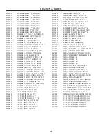
Page 145: ...NARROW CHSL C D CHSL07 8CC4010 D C CH HYD HTCH CYL ATTCH 09 8CC4012 D C CHSL HYD HTCH CLAMP 09 8CC4028 CENTER REAR 20 CHSL 07 8CC4070 WING EXT 2 SHNK D C CHSL L 09 8CC4071 WING EXT 2 SHNK D C CHSL R 09 8CC4075 WING EXT 2 SHNK 28 D C CHL09 8CC4080 WING EXT 4SHNK L D C CHSL 09 8CC4082 WING EXT 4SHNK R D C CHSL 09 8CC4140 LIFTARM 16 20 C DSK CHSL 07 8CC4325 WING LOCK 24 28 D C CHSL 09 8CC5016 CNTR FR...

Page 146: ...4 108 8H2295 MNTNG HEAD SPACER BLOCK 12 8H2315 EXTENSION MNT ARM 6 M94 M108 8H2702 BEARING 1 1 4 SQ FLNG4BLT 8HD0080 PIPE CLAMP 2 1 2 ID PLATED YZ 8HD0150 PIN ADJSTMNT 5 8X9 75 YZ 95 8HD0160 SPRING TINE ADJ COMP ZINC95 8HD0200 U BOLT 1 2 X 2 3 8X 3 9 16 RND 8HD5052 1ST PIPE W LVR 6 104 6 3OR4BR 8HD5054 2ND PIPE W LVR 6 104 6 3OR4BR 8HD5056 3RD PIPEW LVR 6 104 6 3BR93 00 8HD5056Q 3RD PIPE LVR6 3BR1...

Page 147: ...1 5 DIAX1 26EYE YZ 12 8K1900 SEAL GBGI V WALKNG TANDM 01 8K1920 RETAINING RING 2 7 8 INV 00 8K2000 BEARING 211 X 2 02 ID 01 8K2020 RETAINING RING GANG BRNG 84 8K2050 GANG BRNG W HOUSNG 211 X 2 ID 8K2080 CAST BEARNG MNT BASE DRILLD 8K2090 CAST BEARNG PIVOT TUBE DRILLD 8K2120 GANG ROD 2 DIA X 47 8K2128 GANG ROD 2 DIA X 55 CLTR 07 8K2130 GANG ROD 2 DIA X 57 8K2140 GANG ROD 2 DIA X 67 8K2150 GANG ROD ...

Page 148: ... KIT 4 5 X 8 CTD 89 8K8642 SEAL KIT 5 X 8 CTD 2 2 125 ROD 8K8644 SEAL KIT 5 5 X 8 CTD 2 25 ROD 8K8646 SEAL KIT 6 X 8 CTD 2 38 ROD 8K8650 SEAL KIT4X36 CTD 8K9640CYL 90 8K8660 SEAL KIT 5 X 32 36 CTD 89 8K8661 SEAL KIT 5 X 32 W 2 5 SHFT12 8K9102 PIN 1 X 4 CYL FOR1 4 ROLL PIN 8K9106 PIN 1 1 4 X 4 3 8 HRDND 1 4HL 8K9108 PIN 1 1 4 X 5 1 8 HRDND 3 8HL 8K9174 STROKE CNTRL 1 2 2 ROD 96 8K9176 STROKE CNTRL ...

Page 149: ...S2990 HYD HOSE CLAMP LARGE NYLON 8S3059 CAPLUG FITS 2 067 ID TUBE96 8T0100 WASHER SPRG BASE SQHL TRIP 97 8T0320 SHANK UPPER TWO PC DISK 09 8T0322 SHANK LOWER TWO PC DISK 09 8T0400 STL 1 1 8 X 9 5C C LNK GRN 99 8T0500 SHANK CHSL STNDRD BLACK 96 8T0504 SHANK CHSL STNDRD 3 GREEN 09 8T0550 SPRING 4 REAR HTCH PIN 97 8T0600 SPRING CHSL TRIP 700 BLACK96 8T0602 SPRING CHSL TRIP 1050 GREEN03 8T0606 WRENCH ...

Page 150: ...BLT PLTD 96 8T6010 GAUGE WHEEL SCREW TOP 96 8T6020 GAUGE WHEEL JACK HANDL 96 8T6810 PLST BUSH 1 5 8X1 25ID 1 96 8T7500 TRIP ASSY LESS SHANK 700 96 8T7500H TRIP ASSY LESS SHNK 1050 03 8T8100 VALVE SEQUENCE WING FOLD 99 8W1200 U BOLT 1 2 X 2 X 3 1 4 SQ 8W1204 U BOLT 1 2 X 3 X 3 SQ 8W1357 HEX HEAD PLUG 9 16 18 ORB 8W1360 MANIFOLD BLOCK ALUMINUM 10PORT 8W1380 HOLDDOWN HOSE 4 6 WDTH 81 8W1390 HOLDDOWN ...

Page 151: ... 4 10NC X 5 1 2 GR5 YZ 8X0125 BOLT 3 4 10NC X 10 GR5 YZ 8X0128 BOLT 3 4 10NC X 8 1 2 GR8 YZ 8X0130 BOLT 7 8 9NC X 2 GR5 YZ 8X0132 BOLT 7 8 9NC X 2 1 2 GR5 YZ 8X0133 BOLT 7 8 9NC X 3 GR5 YZ 8X0138 BOLT 1 8NC X 5 1 2 GR5 YZ 8X0139 BOLT 1 8NC X 3 GR5 YZ 8X0140 BOLT 1 8NCX7 W 1 5 THDGR5 YZ 8X0141 BOLT 1 8NC X 7 5 GR5 YZ 8X0142 BOLT 1 8NC X 3 5 GR5 YZ 8X0143 BOLT 1 8NC X 5 GR5 YZ 8X0145 BOLT 1 8NC X 10...

Page 152: ...22 CLEVIS PIN 1 2 X 2 1 4 YZ 8X0425 CLEVIS PIN 1 2 X 3 YZ 8X0428 CLEVIS PIN 1 2 X 5 1 4 YZ 8X0432 CLEVIS PIN 1 2 X 6 YZ 8X0440 CLEVIS PIN 5 8 X 3 7 8 YZ 8X0462 CLEVIS PIN 3 8 X 3 W HL YZ 8X0480 HITCH PIN W LYNCH 5 8X4 YZ 8X0492 LYNCH PIN 3 16 X 1 1 4 YZ 8X0520 ROLL PIN 3 16 X 2 ZINC CLEAR 8X0523 ROLL PIN 5 16 X 2 1 2 PLN 8X0528 ROLL PIN 3 8 X 2 1 2 ZINC 8X0605 SET SCRW SQ HD 7 16 14X 1 YZ 8X0632 S...

Page 153: ...addition to the Devils Lake fac tory which enables the company to increase production of truck mounted and pull type supersprayers and rockpickers 1996 1500 square foot office area added to the Maddock plant Company introduces Chisel Plow with floating hitch and 700 trip assembly 1997 16 800 square foot warehouse in Maddock purchased from local business 1999 Company introduces the Ultimate suspend...

Page 154: ...Tillage Land Rollers Packers Sprayers Cultivators Harrows Rock Picker Mounted Attachments 1 800 732 4347 www summersmfg com Field Tested TOUGH ...

Reviews: