Cyclo® BBB4
Operation & Maintenance Manual
15
Cyclo® BBB4
3
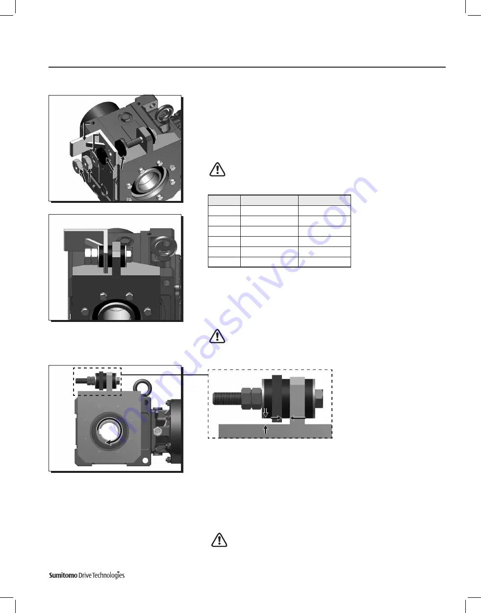
Follow these steps to attach the customer supplied mounting bracket .
• Place rubber bushing and mounting angle bracket on bolt .
• Verify that the mounting angle bracket hole is the correct diameter (see Table 13
in Step 1) .
• Place remaining bushing, washer and two nuts on the bolt .
Do not
over-tighten nuts . Tighten to point where rubber bushings can
still be hand rotated .
4
Confirm that the rubber bushings can still be rotated by hand . This indicates the
bushing has not been over tightened .
Compressed bushings will not allow the bushings to properly absorb the
loads of the shaft mounted gearbox . This can lead to premature failure .
Mounting Angle Bracket must be secured to the machine structure .
5
Confirm the mounting angle bracket
does not interfere with the torque arm .
There should be no metal-to-metal contact between the two during a complete
revolution of the driven equipment .
Metal-to-Metal contact between these two components may lead to
catastrophic failure of the reducer/gearmotor .
Torque Arm Installation,
continued
Flange Mount (Banjo) Type Torque Arm
Washer
Washer
Mounting Angle
Mounting Angle
Bracket (Customer Supplied)
Bracket (Customer Supplied)
Rubber Bushings
Rubber Bushings
Nuts
Nuts
(Customer Supplied)
(Customer Supplied)
During full rotation of driven shaft, there must be
no metal-to-metal contact between mounting angle
bracket and torque arm .
Unit Size
Bracket Tab Bore
Typical Bolt Size
[1]
4A
Ø18mm
M16
4B
Ø18mm
M16
4C
Ø22mm
M20
4D
Ø26mm
M24
4E
Ø33mm
M30
4F
Ø39mm
M36
Table 10 . Flange Mount (Banjo)Torque Arm Bolt Dimensions
Note: [1]
Bolt class should be greater or equal to ISO/JIS Class 8 .8 . Application with multiple start/stops and/or shock
loading should use ISO/JIS 10 .9 at a minimum .


