Section 6
ES-8 MOBILE APPLICATION MANUAL R00
23
MAINTENANCE
6.1
INTRODUCTION
As you proceed in reading this section, it will be easy
to see that the maintenance program for the air
compressor is quite minimal. The Supervisor
monitors the status of the separator element. When
maintenance to this device is required, the
Supervisor will display the appropriate maintenance
message and flash the location LED on the graphics
map as a visual reminder. See instructions for each
item in
Section 6.6: Parts Replacement And
6.2
DAILY OPERATION
Prior to starting the compressor, it is necessary to
check the fluid level in the sump. Should the level be
low, simply add the necessary amount. If the addition
of fluid becomes too frequent, a minor problem has
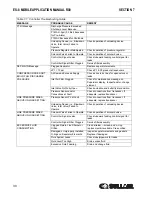
developed which is causing this excessive loss. See
under Excessive Fluid Consumption
for a probable cause and remedy.
After a routine start has been made, a general check
of the overall compressor should bemade to assure
that the compressor is running properly.
6.3
MOTOR BEARING
LUBRICATION
See motor manufacturer’s lubrication instructions.
6.4
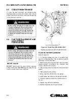
FLUID FILTER
MAINTENANCE
Replace the fluid filter element under any of the
following conditions:
1. As recommended in the Lubrication Guide in
the Specification Section, and below.
2. Every year.
3. Every fluid change.
WARNING
Before doing compressor maintenance, dis-
connect compressor from power source
and lock out power source. Isolate com-
pressor from line pressure by closing rec-
ommended discharge shut-off valve and
releasing all internal pressure from com-
pressor.
WARNING
DO NOT remove caps, plugs, and/or other
components when compressor is running
or pressurized. Stop compressor and
relieve all internal pressure before doing so.
WARNING
Before doing compressor maintenance, dis-
connect compressor from power source
and lock out power source. Isolate com-
pressor from line pressure by closing rec-
ommended discharge shut-off valve and
releasing all internal pressure from com-
pressor.
WARNING
Fluid filter has internal bypass. DO NOT
SUBSTITUTE.
Summary of Contents for 30XH
Page 10: ...NOTES 10 ...
Page 22: ...NOTES 22 ...
Page 33: ...NOTES 33 ...
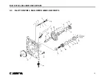
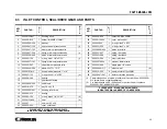
Page 34: ...INLET CONTROL SEAL DRIVE GEAR AND PARTS 34 8 3 INLET CONTROL SEAL DRIVE GEAR AND PARTS ...
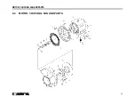
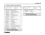
Page 36: ...MOTOR COUPLING FAN AND PARTS 36 8 4 MOTOR COUPLING FAN AND PARTS ...
Page 40: ...COMPRESSOR COOLER SYSTEM AND PARTS 40 8 6 COMPRESSOR COOLER SYSTEM AND PARTS ...
Page 42: ...PNEUMATIC CONTROL SYSTEM AND PARTS 42 8 7 PNEUMATIC CONTROL SYSTEM AND PARTS ...
Page 44: ...CONTROL STARTER MFV 44 8 8 CONTROL STARTER MFV ...
Page 46: ...DECAL GROUP 46 8 9 DECAL GROUP ...
Page 48: ...DECAL GROUP 48 8 9 DECAL GROUP CONTINUED ...
Page 50: ...WIRING DIAGRAM FULL VOLTAGE STANDARD 50 8 10 WIRING DIAGRAM FULL VOLTAGE STANDARD ...
Page 51: ...NOTES 51 ...

