


ES-8 MOBILE APPLICATION MANUAL R00
SECTION 4
18
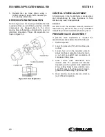
100 psig (6.9 bar). The pressure regulator valve
gradually opens, directing air pressure to the inlet
control valve, reducing air entering the compressor
until it matches the amount of air being used. The
control system functions continually in this manner
between the limits of 100 to 110 psig (6.9 to 7.6 bar)
in response to varying demands from the service
line. The pressure regulator has an orifice which
vents a small amount of air to the atmosphere when
the pressure regulator controls the inlet control valve.
The orifice also bleeds any accumulated moisture
from the pressure regulator.
UNLOAD MODE—IN EXCESS OF 110
PSIG (7.6
BAR
)
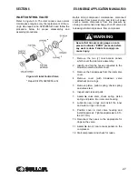
When a relatively small amount or no air is being
used, the service line pressure continues to rise.
When it exceeds 110 psig (7.6 bar), the Supervisor
Control System de--energizes the solenoid valve
allowing sump air pressure to be supplied directly to
close the inlet valve. Simultaneously, the solenoid
valve sends a pneumatic signal to the blowdown
valve. The blowdown valve opens the sump to the
atmosphere, reducing the sump pressure to
approximately 20 to 30 psig (1.4 to 2.1 bar). The
check valve in the air service line prevents line
pressure from returning to the sump.
When the line pressure drops to the low setting(cut-
in pressure; usually 100 psig [6.9 bar] on low
pressure [“L”] compressors and 125 psig [8.6 bar] on
high pressure [“HH”] compressors, 175 psig [12.1
bar] on [“XH”] compressors), Supervisor energizes
the solenoid valve and allows the blowdown valve to
close. The re-energized solenoid valve again
prevents line pressure from reaching the inlet control
valve. Should the pressure begin to rise, the
pressure regulator will resume its normal function as
previously described.
AUTOMATIC OPERATION
For applications with varied periods of time when
there are no air requirements, Supervisor’s
AUTOMATIC mode allows the compressor to
shutdown (time delayed) when no compressed air
requirement is present and restart as compressed air
is needed.
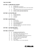
Summary of Contents for 30XH
Page 10: ...NOTES 10 ...
Page 22: ...NOTES 22 ...
Page 33: ...NOTES 33 ...
Page 34: ...INLET CONTROL SEAL DRIVE GEAR AND PARTS 34 8 3 INLET CONTROL SEAL DRIVE GEAR AND PARTS ...
Page 36: ...MOTOR COUPLING FAN AND PARTS 36 8 4 MOTOR COUPLING FAN AND PARTS ...
Page 40: ...COMPRESSOR COOLER SYSTEM AND PARTS 40 8 6 COMPRESSOR COOLER SYSTEM AND PARTS ...
Page 42: ...PNEUMATIC CONTROL SYSTEM AND PARTS 42 8 7 PNEUMATIC CONTROL SYSTEM AND PARTS ...
Page 44: ...CONTROL STARTER MFV 44 8 8 CONTROL STARTER MFV ...
Page 46: ...DECAL GROUP 46 8 9 DECAL GROUP ...
Page 48: ...DECAL GROUP 48 8 9 DECAL GROUP CONTINUED ...
Page 50: ...WIRING DIAGRAM FULL VOLTAGE STANDARD 50 8 10 WIRING DIAGRAM FULL VOLTAGE STANDARD ...
Page 51: ...NOTES 51 ...


