


ES-8 MOBILE APPLICATION MANUAL R00
SECTION 6
26
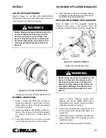
5. Reinstall the cap. Hand tighten using a
100mm maximum length, 6mm diameter pin
in the radially drilled hole.
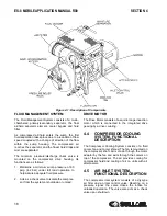
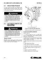
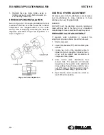
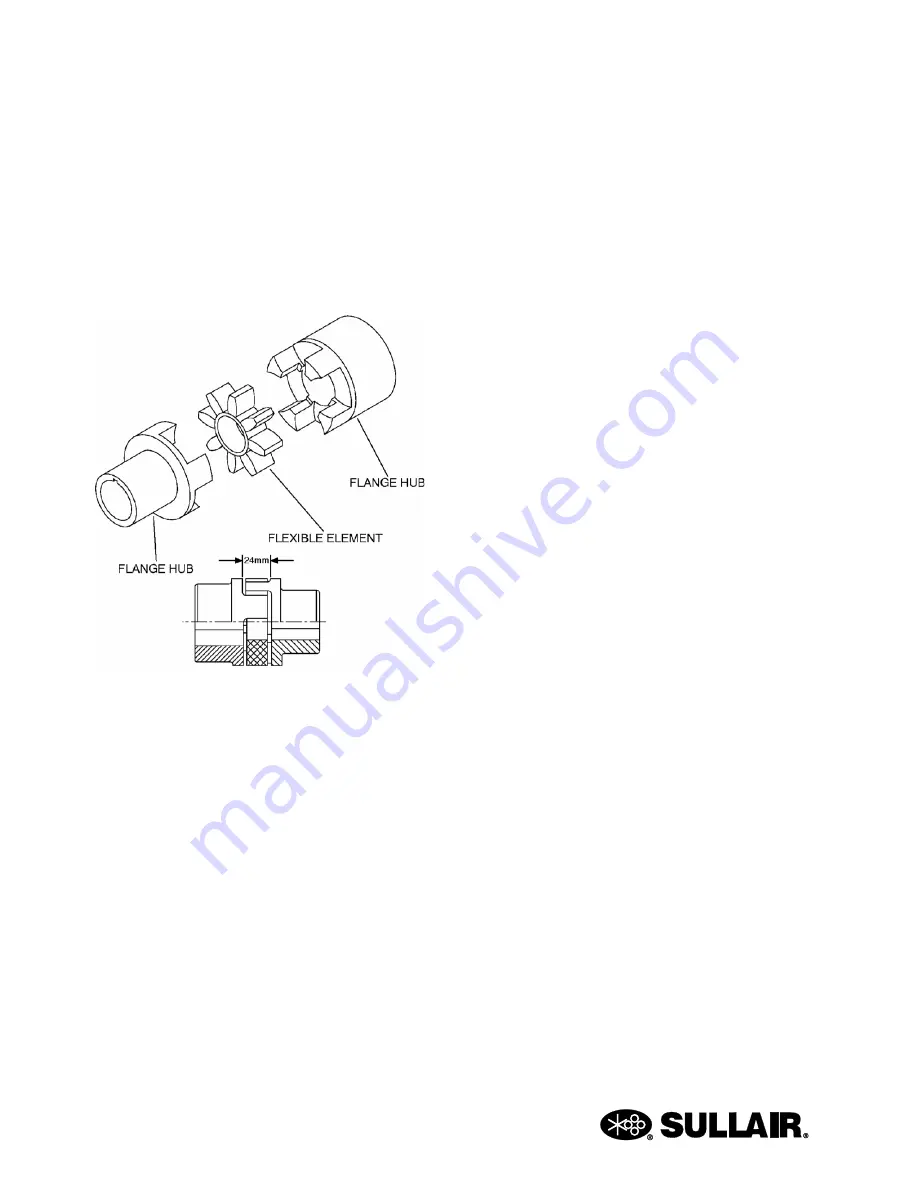
DRIVE COUPLING INSTALLATION
. For coupling installation the tools
required will be one set of Allen wrenches. All ES-8
compressors are flange-mounted to the motor
making them self-aligning, eliminating the need for
alignment procedures. Proper hub separation is s
hown in
.
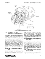
CONTROL SYSTEM ADJUSTMENT
All components in the Control System are designed
and manufactured to close tolerances to help
eliminate any need for adjustments.
DANGER
DO NOT touch the electrical contacts, terminal or
leads with any part of the body or any uninsulated
metallic object. Severe electrical shock may occur.
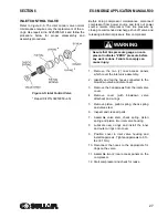
PRESSURE VALVE ADJUSTMENT
If pressure valve adjustment is required the
adjustment procedure below should be followed:
1. Start compressor.
2. Lower line pressure (P2) until machine goes
on load.
3. Loosen hex nut on the regulator valve to
adjust machine modulation. Adjust screw in
or out until on load/off load modulation of
compressor takes place.
4. Close service valve downstream from
receiver tank. The pressure will increase
depending on the regulator valve adjustment
screw setting. Adjust screw until line pres-
sure (P2) rises to the Supervisor II prepro-
grammed off load setting. Tighten hex nut.
5. Open service valve and observe correct on
load/ off load modulation.
Figure 6-4: Hub Separation
Summary of Contents for 30XH
Page 10: ...NOTES 10 ...
Page 22: ...NOTES 22 ...
Page 33: ...NOTES 33 ...
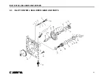
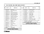
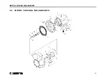
Page 34: ...INLET CONTROL SEAL DRIVE GEAR AND PARTS 34 8 3 INLET CONTROL SEAL DRIVE GEAR AND PARTS ...
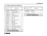
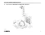
Page 36: ...MOTOR COUPLING FAN AND PARTS 36 8 4 MOTOR COUPLING FAN AND PARTS ...
Page 40: ...COMPRESSOR COOLER SYSTEM AND PARTS 40 8 6 COMPRESSOR COOLER SYSTEM AND PARTS ...
Page 42: ...PNEUMATIC CONTROL SYSTEM AND PARTS 42 8 7 PNEUMATIC CONTROL SYSTEM AND PARTS ...
Page 44: ...CONTROL STARTER MFV 44 8 8 CONTROL STARTER MFV ...
Page 46: ...DECAL GROUP 46 8 9 DECAL GROUP ...
Page 48: ...DECAL GROUP 48 8 9 DECAL GROUP CONTINUED ...
Page 50: ...WIRING DIAGRAM FULL VOLTAGE STANDARD 50 8 10 WIRING DIAGRAM FULL VOLTAGE STANDARD ...
Page 51: ...NOTES 51 ...