Section 2
DESCRIPTION
8
in the Parts List portion of this manual. The
compressor unit discharges the compressed
air/fluid moisture through a discharge check valve
into the combination receiver/sump. The discharge
check valve prevents air in the receiver from return-
ing to the compression chamber after the compres-
sor has been shut down. The receiver has three
functions:
• It acts as a primary fluid separator.
• Serves as the compressor fluid sump.
• Houses the final fluid separator elements.
The compressed air/fluid mixture enters the receiv-
er and is directed against the ends of the tank. The
direction of movement is changed and its velocity
significantly reduced, thus causing large droplets of
fluid to form and fall to the bottom of the
receiver/sump. The fractional percentage of fluid
remaining in the compressed air collects on the sur-
faces of the dual separator elements as the com-
pressed air flows through them. Two return lines (or
scavenge tubes) lead from the bottom of each sep-
arator element to the interstage of the compressor
unit. Fluid collecting on the bottom of each separa-
tor is returned to the compressor by a pressure dif-
ference between the receiver and the compressor.
Sight glasses are located in the return lines to
observe this fluid flow. There are also orifices in this
return line (protected by strainers) to assure proper
flow. By pressing the
+
pads on the
Supervisor Controller, the operator may monitor the
condition of the separator elements by reading dif-
ferential pressure on the digital display. At a differ-
ential of 10 psid (0.7 bar) or greater, the operator
will be told to service the separator element. At this
time, separator element replacement is necessary.
The receiver is an ASME pressure vessel. A combi-
nation minimum pressure/check valve, located
downstream from the separator, assures a mini-
mum receiver pressure of 160 psig (11 bar) during
full load operation. This pressure is necessary for
proper air/fluid separation and proper fluid circula-
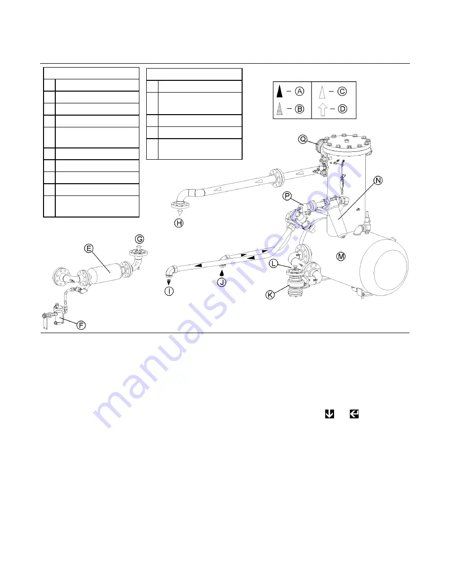
Figure 2-2 Compressor Cooling, Lubrication and Discharge System (Typical)
KEY
A
FLUID (LINE)
B
AIR/FLUID (LINE)
C AIR (LINE)
D WATER (LINE)
E
MOISTURE
SEPARATOR
F
TRAP DRAIN
G FROM AFTERCOOLER
H TO AFTERCOOLER
J
FROM OIL COOLER
K
DISCHARGE CHECK
VALVE
KEY (CONTINUED)
L
FROM UNIT
M
SUMP/SEPARATOR
TANK
N MAIN FLUID FILTER
P
OIL STOP VALVE
Q
MINIMUM PRESSURE/
CHECK VALVE
Summary of Contents for LS20T 1100 CFM
Page 18: ...Section 2 DESCRIPTION 12 Figure 2 3B Control System Diagram START...
Page 19: ...Section 2 DESCRIPTION 13 Figure 2 3C Control System Diagram MODULATION...
Page 20: ...Section 2 DESCRIPTION 14 Figure 2 3D Control System Diagram FULL LOAD...
Page 21: ...Section 2 DESCRIPTION 15 Figure 2 3E Control System Diagram UNLOAD...
Page 44: ...NOTES 38...
Page 104: ...Section 9 ILLUSTRATIONS AND PARTS LIST 98 02250146 367R00 9 19 CONTROL START SYSTEM...
Page 106: ...Section 9 ILLUSTRATIONS AND PARTS LIST 100 02250146 367R00 9 19 CONTROL START SYSTEM...
Page 108: ...Section 9 ILLUSTRATIONS AND PARTS LIST 102 02250138 633R00 9 20 CONTROL PANEL...
Page 110: ...Section 9 ILLUSTRATIONS AND PARTS LIST 104 02250139 119R01 9 21 ENCLOSURE...
Page 112: ...Section 9 ILLUSTRATIONS AND PARTS LIST 106 02250139 119R01 9 21 ENCLOSURE...
Page 114: ...Section 9 ILLUSTRATIONS AND PARTS LIST 108 9 22 DECAL GROUP...
Page 116: ...Section 9 ILLUSTRATIONS AND PARTS LIST 110 9 22 DECAL GROUP...
Page 118: ...Section 9 ILLUSTRATIONS AND PARTS LIST 112 9 22 DECAL GROUP...
Page 120: ...Section 9 ILLUSTRATIONS AND PARTS LIST 114 9 23 DECAL LOCATIONS OPEN AIR COOLED...
Page 122: ...Section 9 ILLUSTRATIONS AND PARTS LIST 116 9 24 DECAL LOCATIONS OPEN WATER COOLED...
Page 124: ...Section 9 ILLUSTRATIONS AND PARTS LIST 118 9 25 DECAL LOCATIONS REMOTE COOLER...
Page 126: ...Section 9 ILLUSTRATIONS AND PARTS LIST 120 9 26 DECAL LOCATIONS CONTROL BOX...
Page 128: ...Section 9 ILLUSTRATIONS AND PARTS LIST 122 9 27 ENCLOSURE DECALS...
Page 145: ...NOTES 139...


