background image


46

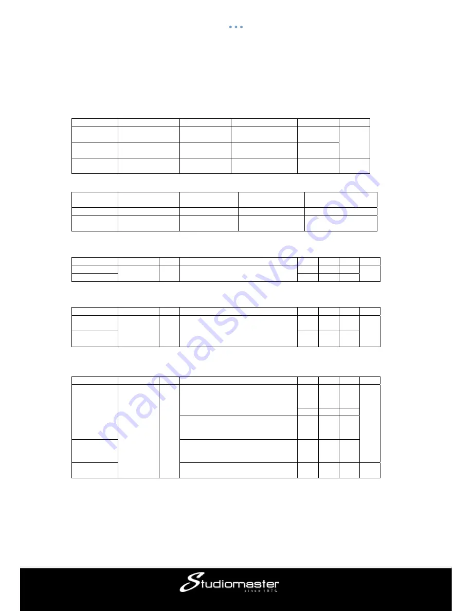
digiLiVE16 SPECIFICATIONS 

Input Characteristics 

Output impedance of signal generator:150

Ω


Input Input 

Impedance 

Connector

Maximum Input

Sensitivity Range 

MIC INPUT 

1.5K

Ω


XLR 
(Balanced)


+16 dBu

to 

+60dBu 

60dB 

LINE INPUT 

10K

Ω


TRS

(Balanced)

+30 dBu

-20 to 
+40dBu 

ST INPUT 

10K

Ω


TRS

(Balanced)

+22dBu

-20 to 
+20dBu 

40dB 


Output Characteristics


Output Output 

Impedance 

Connector

Residual Output 
Noise 

Maximum Output 

BUS OUT 

470

Ω


XLR (Balanced)

-90 dBu

+18 dBu 

PHONES 
OUT 

100

Ω


TRS

(Unbalanced)

-92 dBu

+22 dBu 


Frequency Response 

Fs= 48 kHz @20 Hz–20 kHz, referenced to the nominal output level @1 kHz 

Input 

Output

 RL 

Conditions

Min

TYP 

Max Unit 

MIC INPUT 

BUS 

600

Ω


0dBu @20 Hz–20 kHz, GAIN: 0dB
 

-0.2

0 0.1 

dB 

ST INPUT 

-0.2

0.1 


Total Harmonic Distortion 

Fs= 48 kHz @ Total Harmonic Distortion is measured with a 18 dB/octave filter @80 kHz 

Input 

Output

 RL 

Conditions

Min

TYP 

Max Unit 

MIC INPUT 

BUS 

600

Ω


0dBu @20 Hz–20 kHz, GAIN: 0dB
 

0.00

 % 

ST INPUT 

0.00


Hum & Noise 

Fs= 48 kHz, EIN= Equivalent Input Noise@ 20Hz–20kHz 

Input 

Output

 RL 

Conditions

Min

TYP 

Max Unit 

INPUT 1-16 
 

BUS 
 

600

Ω


Rs= 150

Ω

,GAIN: Max. Master fader 

at nominal level and one Ch fader at 
nominal level. 

-
126 
EIN 

 dBu 

-70  

Rs= 150

Ω

,GAIN: Min. Master fader at 

nominal level and one Ch fader at 
nominal level. 

-88  

All INPUT 

Rs= 150

Ω

,GAIN: Min. Master fader at 

nominal level and all Ch1-16 in faders 
at nominal level. 

-78  

 Residual 

Output Noise, BUS Master 

Off 

-90  


Hum & Noise are measured with a 6 dB/octave filter @12.7 kHz; equivalent to a 20 kHz filter with infinite 
dB/octave attenuation. 


Summary of Contents for digiLiVE 16

Page 1: ...Issue 1 0 digiLiVE 16 Digital Mixing Console User Guide...

Page 2: ...t Stage Subpage 15 Parametric EQ Subpage 16 Dynamics Subpage 16 Bus Send Subpage 16 Output Stage Subpage 16 Output busses 17 Input Stage Subpage 18 Parametric EQ Subpage 21 Output Stage Subpage 23 Set...

Page 3: ...es the digiLiVE 16 a pleasure to work with leaving you to concentrate on the show and not the equipment READ THE USER GUIDE The Studiomaster design philosophy has always been to provide the controls a...

Page 4: ...ecomes damaged in any way 3 Never operate without or remove the safety ground earth from the A C power cord mains lead 4 Do not attempt to remove any screws or panels There are no user serviceable par...

Page 5: ...ts along with stereo S PDIF and stereo USB playback The layer can be changed at any time by pressing INPUT1 8 or INPUT9 12 ST USB on the front panel or by sliding left right on the touch screen while...

Page 6: ...el information Double click e g to edit the name of the selected channel through an on screen soft keyboard that will pop up Input Stage Sub page Switch channels Press the arrow buttons to choose the...

Page 7: ...activated by pressing the main encoder The frequency range is 16 Hz to 400 Hz with 16 Hz being default Insert Press an effect module button to insert it prior to the channels EQ Each effect module can...

Page 8: ...selecting it through touch and subsequently dragging it to point towards the desired value The selected soft encoder can also be adjusted using the blue lit main encoder on the front panel Pressing an...

Page 9: ...s settings A soft keyboard will pop up on screen to enter a name for the setting Finally press confirm to save the setting or cancel to abandon Gate IN Single press to enable the Gate press again to d...

Page 10: ...output volume of the signal back after compression Parameter Adjustment Adjust the Compressor s parameter on screen by selecting and dragging the corresponding slider or use the blue lit main encoder...

Page 11: ...lected channel so by default all channels work independent using their own signal as a control for the compression Bypass Single press for full Dynamics Bypass Gate and Compressor press again to switc...

Page 12: ...post fader send to a bus Pre fader does not include the fader gain value which can be useful for effect sends or monitoring Default is pre fader PAN control Controls the panning into a stereo bus Defa...

Page 13: ...value Solo This is a copy of the hardware button on the front panel Press to enable or disable signal sent to the solo monitor bus Mute Like Solo this is a copy of the hardware button on the front pan...

Page 14: ...ions The sub pages can be closed through the red close button in the upper right corner Input Stage Shows status of SUM phase delay HPF High Pass Filter and effect insert EQ Shows parametric EQ graph...

Page 15: ...ly contains the voice of a recording and create a simple karaoke effect Trim Allows digital amplification or attenuation of the input signal Press to enable default is disabled Adjust the Trim using t...

Page 16: ...page In case of ST1 and ST2 this page is the same as for the MIC channels with any settings being applied to both channels of the stereo signal For S PDIF and USB channels there is no dynamic section...

Page 17: ...While the left side of the page gives a full overview of all in and outputs of the console the right side shows the Master L R output strip which in functionality follows exactly the stereo Busses 5 8...

Page 18: ...given bus are shown here Output Stage Displays the name Pan BAL value Solo Mute delay fader and meter level information Double click e g to edit the name of the selected channel through an on screen...

Page 19: ...wtch Switches between pre and post fader send to a bus Pre fader does not include the fader gain value which can be useful for effect sends or monitoring Default is pre fader PAN control Controls the...

Page 20: ...or two effect modules inserted subsequently with the order of the modules being determined by the order of selection When a selected module is used in another channel or bus a pop up window will warn...

Page 21: ...umbered points on the EQ curve indicate the position of the four EQ bands Each band can be selected by taping on the corresponding point or through the select buttons Adjustment of the selected band c...

Page 22: ...Default values are HF 4kHz HMF 1kHz LMF 200 Hz LF 60Hz The terms HF HMF LMF and LF only refer to the initial setting of the bands there is no restriction in setting the EQ bands so after setup LF may...

Page 23: ...ms default is 0ms PAN BAL control Controls the panning into master L R Default is 50 50 middle The PAN value can be changed through the on screen encoder or by turning the main encoder on the control...

Page 24: ...post fader sends of the active channel to all busses including master lr Fader control This is a copy of the physical fader of the selected channel You can change the on screen fader through touch an...

Page 25: ...Outputs then the 44 1 KHz light on and the 48 KHz light off The default is always 48 0 KHz after rebooting the system Delay Unit Single press any one among three ms ft and m buttons to choose the mea...

Page 26: ...le press SetupWifi More Portable hotspot Set up Wi Fi hotspot A window will pop up like below Please enter the network name in Network SSID for example Digilive16 as in the picture Set the password in...

Page 27: ...e from App Store and install it on your pad 2 Select the network Digilive16 which was previously configured on the mixing console on the WIFI interface on your iPad 3 Open the APP Digilive16 press NET...

Page 28: ...tness Adjust the brightness of the touch screen Six units to indicate the level of brightness the default is three units After rebooting the system the unit of brightness is always what you set before...

Page 29: ...h the digiLiVE will reboot and your software will then be updated Factory Reset Single press Factory Reset button a dialog pops up Do you want to do a Factory Reset This will reset your settings to fa...

Page 30: ...hite crosses If the calibrations messes up you will have to connect a mouse to the evice and repeat it press Calibrate and calibrate your screen following the tip information Please pay attention that...

Page 31: ...r output busses the 8 analogue outputs can select any one of the 14 busses After rebooting the system the Patch setting is always what you set before you had powered off the console last time Meter Pa...

Page 32: ...the effect module to open a subpage of parameter settings for this module Single press the close button red X on the subpage to exit and return to FX page Bus selection Single press the dropdown butt...

Page 33: ...dropdown list Chorus Slow Chorus Fast Flanger Slow Flanger Fast Celeste Slow Celeste Fast Rotor Slow Rotor Fast Dry Wet Ranges from 0 to 100 with a default 0 Adjust the parameter of Dry Wet by draggi...

Page 34: ...r or on the touch screen fine tuning can be activated by pressing the main encoder knob Double press the parameter frame to set it as default Other parameters Speed ranges from 50 to 200 with a defaul...

Page 35: ...the control panel EQ LS Curve chart displays the LS curve Gain ranges is 18 dB with a default 0 dB Adjust the Gain by turning the main encoder or on the touch screen fine tuning can be activated by p...

Page 36: ...alue press at least three times to set Delay Time ranges from 0 to 2000 ms with a default 750ms Adjust the time parameter by turning the main encoder or on the touch screen fine tuning can be activate...

Page 37: ...b from the dropdown list Hall Bright Hall Warm Room Bright Room Warm Plate Bright Plate Warm Dry Wet Ranges from 0 to 100 with a default 0 Adjust the parameter of Dry Wet by dragging the slider or tur...

Page 38: ...vated by pressing the main encoder knob Double press the parameter frame to set it as default Other parameter Time the parameter can set the basic size of simulated room ranges from 0 to 15s with a de...

Page 39: ...ingle press the Save button after you have adjusted EQ settings then select the library file there are 16 libraries Preset 1 Preset16 which can be edited through the soft keyboard Lastly press confirm...

Page 40: ...the middle position of stroke if they are used to control The default is disabled Fader selection button 1 8 Single press the button to control the gains of frequency points with 8 faders on the panel...

Page 41: ...to the current scene Load Load scene When selecting a scene single press the button to load the scene Import load a scene from a USB drive Single press the button a dialog pops up Compressed file lis...

Page 42: ...ou have seen the scene you want Next browse next scene Single press Load to load the current scene once you have seen the scene you want Recorder Page The recorder page will playback recorded material...

Page 43: ...ter L R bus to the USB drive in WAV format Press again to stop the recording and save the file to your USB drive Monitor Page The page contains settings for Oscillator Monitor Phones and Solo Oscillat...

Page 44: ...e Press the button to lighten the red LED button and mute monitor signal press again to disable mute The default is disabled Note The headphone signal and monitor signal are the same which are subject...

Page 45: ...uthorisation RA number Pack the unit in its original carton to protect it from shipping damage You must have the Returns Authorisation number clearly marked on the outside of the carton or we may refu...

Page 46: ...Hz 20 kHz GAIN 0dB 0 2 0 0 1 dB ST INPUT 0 2 0 0 1 Total Harmonic Distortion Fs 48 kHz Total Harmonic Distortion is measured with a 18 dB octave filter 80 kHz Input Output RL Conditions Min TYP Max U...

Page 47: ...Hz Output Function Function Parameter Delay 0 msec to 200 msec Insert 2Modul 2Delay 2Reverb 2GEQ 4 Band Equalizer Frequency 20 Hz to 20 kHz Gain 18 dB to 18 dB Q 0 5 to 10 0 Low Low Mid High Mid High...

Page 48: ...STUDIOMASTER Unit 11 Torc MK Chippenham Drive Milton Keynes MK10 0BZ United Kingdom Tel 44 0 1908 281072 Email enquiries studiomaster com Web www studiomaster com...

Reviews: