background image

- 3 -

Cont ...

CONTENTS 

Page

Checklist  . . . . . . . . . . . . . . . . . . . . . . . . . . . . . . . . . . . . . . . . . . . . . . . . . . . . . . . . 4

Pre-Installation  . . . . . . . . . . . . . . . . . . . . . . . . . . . . . . . . . . . . . . . . . . . . . . . . . . . 5

Important Facts - read before commencing installation   . . . . . . . . . . . . . . . . . . . 6

Location  . . . . . . . . . . . . . . . . . . . . . . . . . . . . . . . . . . . . . . . . . . . . . . . . . . . . . . . . 7

Electrical Installation  . . . . . . . . . . . . . . . . . . . . . . . . . . . . . . . . . . . . . . . . . . . . . . . 10

Commissioning  . . . . . . . . . . . . . . . . . . . . . . . . . . . . . . . . . . . . . . . . . . . . . . . . . . . 12

Maintenance  . . . . . . . . . . . . . . . . . . . . . . . . . . . . . . . . . . . . . . . . . . . . . . . . . . . . . 14

Technical Speci

fi

 cation  . . . . . . . . . . . . . . . . . . . . . . . . . . . . . . . . . . . . . . . . . . . . . 15

Trouble Shooting   . . . . . . . . . . . . . . . . . . . . . . . . . . . . . . . . . . . . . . . . . . . . . . . . . 16

Guarantee  . . . . . . . . . . . . . . . . . . . . . . . . . . . . . . . . . . . . . . . . . . . . . . . . . . . . . . . 19

Summary of Contents for Jet 55-45 B

Page 1: ...ruction booklet with the owner as it contains important guarantee maintenance and safety information Read this manual carefully before commencing installation This manual covers the following products...

Page 2: ...aged from 8 years and above and persons with reduced physical sensory or mental capabilities or lack of experience and knowledge if they have been given supervision or instruction concerning use of th...

Page 3: ...age Checklist 4 Pre Installation 5 Important Facts read before commencing installation 6 Location 7 Electrical Installation 10 Commissioning 12 Maintenance 14 Technical Specification 15 Trouble Shooti...

Page 4: ...ture above Item Description Qty Item Description Qty Pump 1 Pressure vessel 1 Fig 1 A A B B IMPORTANT With the pump removed from its packaging check for any damage prior to installation If any damage...

Page 5: ...must be taken when re positioning the pressure vessel to ensure no strain is placed upon the pressure switch or reed switch cables The flow switch assembly can now be carefully rotated to an alternati...

Page 6: ...should be taken in the design of pipework runs to minimize the risk of air locks e g use drawn bends rather than 90o bends 1 18 DO NOT introduce solder flux to pumps or pump parts manufactured from pl...

Page 7: ...mp must be positioned as close to the water source as possible The pump has a side mounted terminal box Ensure the pump is mounted in a position that allows easy access to the box if required 2 18 Amb...

Page 8: ...MP MOUNTED BELOW WATER SOURCE 2 25 Water supply Must be made via a tank connector offering a dedicated supply direct to the pump Fig 4 Cold water pump Static inlet pressure Min 1 m Max 5 m Static outl...

Page 9: ...possible distance and ensure there is a constant rise from the water source to the pump Any high spots will cause air pockets to form reducing system efficiency The suction hose must be a minimum of 2...

Page 10: ...earth point located in the terminal box 3 17 Pipework Copper or metallic pipework must have supplementary earth bonding where the continuity has been broken by flexible hoses or plastic components no...

Page 11: ...ed 3 21 Wiring Diagram The supply cord and internal wiring within the terminal box are routed and secured to ensure compliance with the electrical standard EN 60335 1 It is essential that any disturba...

Page 12: ...be a small time delay before the pump stops which is normal 4 COMMISSIONING 4 11 System Flushing The pipework system should be flushed out prior to the pump being connected to ensure any contaminants...

Page 13: ...or leaks whilst pump running and stationary before leaving the installation unattended Do not run pump without guards and terminal box lid correctly fitted The pump chamber must be full of water at al...

Page 14: ...vessel to pump hand tight to achieve a water tight connection Ensure sealing O ring is in place h Close all system outlets open inlet and outlet isolating valves i After maintenance is completed refe...

Page 15: ...formance 10 l min 3 1 bar 3 2 bar Performance 40 l min 1 2 bar 2 2 bar Maximum flow 53 l min 75 l min Manimum static inlet pressure 0 1 bar 1 metre Maximum static inlet pressure 0 5 bar 5 metres Maxim...

Page 16: ...is fitted correctly in location groove Faulty reed switch or P C B pressure switch If pump continues to run this indicates a closed circuit in either the flow switch reed or P C B in the terminal box...

Page 17: ...e water starvation condition remains present the pump will then stop operation after a 1 minute period 6 The pump will remain in the off condition for a period of 5 minutes 7 The pump will then re sta...

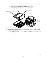
Page 18: ...l box lid ensuring no cables are trapped Re fit the four terminal box lid retaining screws tighten to 0 8 Nm 7 14 Environment Protection Your appliance contains valuable materials which can be recover...

Page 19: ...tc If you have any doubt about removing a pump please consult a professional 44 0 844 98 000 97 Proof of purchase should accompany the returned unit to avoid delay in investigation and dealing with yo...

Page 20: ...BS EN 61000 3 3 BS EN 61000 4 2 BS EN 61000 4 3 BS EN 61000 4 4 BS EN 61000 4 5 BS EN 61000 4 6 BS EN 61000 4 11 1999 519 EC BS EN 62233 2011 65 EU IT IS HEREBY CERTIFIED THAT THE STUART ELECTRIC MOT...

Reviews: