


- 12 -
Cont ...
6 MAINTENANCE
6.11 Turn off water supplies to the pump and release pressure by
opening water outlets before attempting maintenance.
6.12
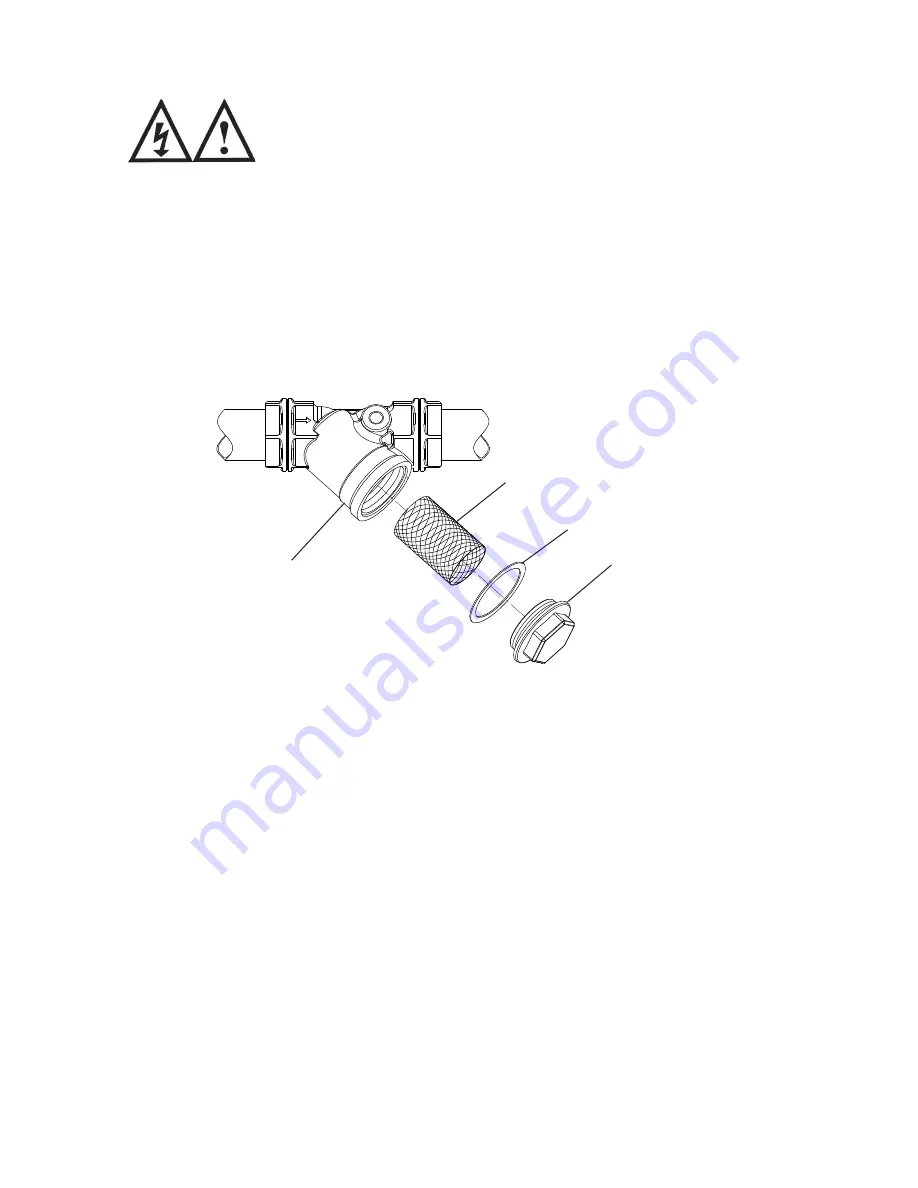
Inlet strainer:
Incorporated in the strainer is a removable gauze filter which
may require periodic cleaning. The frequency of this operation is dependent upon
installation
conditions.
The strainer is located in the inlet pipework to the pump (Fig. 8). The gauze filter
is removed as follows:-
a) Isolate pump electrically.
b) Release all system pressure.
c) Isolate water supply.
d) Remove screwed hexagonal plug from strainer body taking care to collect or
absorb any residual water (Fig. 8).
e) Remove and clean stainless steel gauze filter.
f) Reassemble gauze and secure plug tightly.
g) Turn on water supplies, connect power supply and test.
6.13
Pressure vessel:
The pressure vessel should be checked once every 6 months
to have its air charge checked or replenished, this should be carried out
as
follows:-
a) Isolate pump electrically.
b) Isolate the water supply by closing the appropriate isolating valves.
c) Release system water pressure by opening an outlet on the system.
d) Disconnect hose fitted to pressure vessel.
e) Check air charge at Schrader valve (Fig. 9) using a tyre pressure gauge.
f) Replenish air charge by injecting air into the vessel via the Schrader valve
using a car or bicycle pump (Fig. 9).
g) Re-connect hose to pressure vessel to achieve a water tight connection.
Ensure fibre washer seal is in place.
h) Close all system outlets, open inlet and outlet isolating valves.
i) After maintenance is completed refer to Section 5 - Commissioning for
instructions on re-starting pump.
Strainer
Gauze
Gasket
Hex plug
Fig. 8


