29
M2-H
Description, Care and Maintenance
Internal Tank Jets
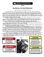
The Internal Tank Jets (Fig.11a) are supplies with the M2 unit, and are installed (by the customer) inside the
reservoir tank, to keep the slurry product in the tank moving. This function assures the elimination of dead
spots in the tank and a consistent mixture of fluid.
The internal tank jets are connected together in series, usually by a manifold design, (suggested by STS)
were all jets receive the same amount of fluid and pressure. This manifold design is supplied with fluid from
one of the outlets on the filter / shear housing (Fig.11b). The outlet has a ball valve to control the flow,
(Fig.11b) and should always be in the open position, unless you are cleaning the filter / shear (described
earlier) or performing repairs on the system. If the valve is not closed, when preforming these tasks, a
siphoning action can occur, pulling fluid from the tank and into the external piping. The internal tank jets
requires little or no maintenance and will only require attention if they become clogged. Flushing the entire
system daily with clear water should eliminate any problems with this piece of the system. The fluid passing
through the internal tank jets is at a very high pressure and extreme caution should be used when viewing
the inside of the tank.
The internal tank jets also acts as a relief valve to the system and relieves the pressure spikes caused when
the flow to the drill rig or second reservoir tank is interrupted.
Fig.11a
Fig.11b
CAUTION
TO ENTER THE TANK is not recommended
Personal injury could result from
the presents of hazardous fumes,
remaining fluid or unit start-up.
CAUTION
NEVER OPERATE THE MIXING
unit with the tank lid open.
DANGER
NEVER ATTEMPT REPAIRS
OR DISASSEMBLY
without shutting off the hydraulic
power source (customer supplied)
Serious personal inj ury will result.
CAUTION
WHEN THE UNIT
IS IN OPERATION,
the fluid in the piping may reach
pressures up to 50 p.s.i.
Summary of Contents for M2-H
Page 2: ...2 This page left blank intentionally ...
Page 13: ...13 ...
Page 18: ...18 M2 H Identifying Your Machine Components Location of Tags and PIN Plates ...
Page 19: ...19 SECTION II Description Care and Maintenance ...
Page 31: ...31 SECTION III Set up and Installation of Unit in Detail ...
Page 33: ...33 SECTION IV Operating the M2 Unit ...
Page 41: ...41 SECTION V Troubleshooting the M2 Unit ...
Page 44: ...44 SECTION VI Periodic Maintenance Repair Information ...
Page 49: ...49 SECTION VII OEM Repair Information ...
Page 62: ...62 ...
Page 63: ...63 ...
Page 64: ...64 ...
Page 68: ...68 SECTION VIII Parts Manual ...


