M1
DC-motor
A1
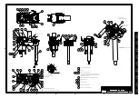
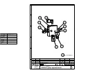
Control Board
Sample Mover Motor
Solenoid Valve
Solenoid Valve
24Vdc in
+5Vdc regulator
CAN interface
RS232 interface
4x 24Vdc/2,5A outputs
1x bidirectionel
0-24Vdc / 6,5A
motordriver
circuit
1x bidirectionel
24Vdc/0,3A
motor driver
with brake
function
5x dig. inputs
TegraForce-1/3
Plug in connection for
TegraDoser-1
Test Socket
Connection to
TegraPol
B1
Speed
feedback
Speed feedback
B2
Namur
Sensor
Reset Circuit
NEC V850 uP Circuit
Socket for initial
programming
Non Volatile Memory
Input for
position
sensor
Y1
Y2
XS1
W2
9 poles flatcable
28AWG
XS2
Pressure increase
Pressure decrease
Current feedback
+
9 poles
D-sub male
X2-1
X2-2
X2-3
X2-4
X2-5
X2-6
X2-7
X2-8
X2-9
X2-10
X2-11
X2-12
X7-1
X7-2
X4-3
X4-1
X4-2
X4-4
X5-1
X1-3
X1-2
X1-5
X1-4
X1-1
(+24V)
(CAN-LO)
(CAN-HI)
(0 V)
(CHASSIS)
X6-2(0 V)
(TX)
(RX)
X6-3
X6-4
X6-1
X4-5
Head in correct
possition
X4-6
GY/WH/BN
BK/BK/BU
WH
GN
RD
BK
BK
RD
BK
RD
4 shield
9 poles
D-sub
male
Shield
CAN-H
CAN-L
X1
+24 V
W1
GND
9-pol. D-Sub.
Female
3 Shield
W3
X5-9
BK
BN
RD
Shield
BK
BN
RD
OG
Shield
TegraForce-1: 35W
TegraForce-3/5: 118W
RD
BK
BN = BROWN
BU = BLUE
GN = GREEN
YE = YELLOW
COLOR CODES (IEC757):
PK = PINK
BK = BLACK
VT = VIOLETT
OG = ORANGE
WH = WHITE
GY = GREY
RD = RED
Ver.C: (FTH 04-07-2002)
- Color codes corrected,
- Brake resistor added
24Vdc/2,5A output
X8-1
X8-2
Brake Resistor
TegraForce-1: 20R/40W
TegraForce-3: 10R/70W
On some early TegraForce-1
and TegraForce-3 models the
brake resistor is connected
to X2-11/12
FTH / FTH
R1
BU1
BU2
Ver.D: (FTH 09-02-2009)
- Working Light added
- Emengency Stop functionality added
- TF-5 now on a separate diagram
Working Light
(24V LED lamp)
HL1
+45 44 600 800
STRUERS A/S
15573100
Monday, February 09, 2009
1
1
A2
Pederstrupvej 84
DK-2750 Ballerup
Denmark
TegraForce-1/3, Circuit Diagram
<Cage Code>
D
Size
Scale
CAGE Code
DWG NO
Rev
Sheet
of
5
9
4
8
3
7
2
6
1
5
9
4
8
3
7
2
6
1
5
9
4
8
3
7
2
6
1


