background image

Discotom-6 
Mode d'emploi 


Discotom-6 
Fiche de sécurité 
 
A lire attentivement 
avant utilisation 


1. 

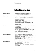
L'utilisateur doit être pleinement instruit dans l'usage de la machine et 
de ses meules de tronçonnage selon le mode d'emploi et les 
instructions se rapportant aux meules de tronçonnage. 

2. 

La machine doit être placée sur une table sûre et stable. Toutes les 
fonctions de sécurité et les écrans de protection de la machine doivent 
être en parfait état de fonctionnement. 

3. 

Utiliser uniquement des meules de tronçonnage intactes. Les meules 
de tronçonnage doivent être homologuées pour 50 m/s. 

4. 

Respecter les règles de sécurité en vigueur pour la manipulation, le 
mélange, le remplissage, le vidage et l'élimination de l'additif pour le 
liquide de refroidissement. 

5. 

L'échantillon doit être bien fixé dans le dispositif de bridage rapide ou 
similaire. Les échantillons grands ou aigus doivent être manipulés avec 
précaution. 

6. 

La poignée de tronçonnage doit être abaissée lentement et avec 
précaution afin d'éviter une brisure de la meule de tronçonnage. 

7. 

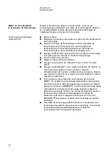
Struers recommande l'utilisation d'un dispositif d'aspiration, car les 
matériaux de tronçonnage peuvent exhaler des gaz ou des poussières 
toxiques. 

8. 

Les rideaux de caoutchouc du côté gauche permettent de tronçonner 
des pièces longues.  

9. 

Ne jamais faire passer la main à travers le rideau de caoutchouc 
pendant le fonctionnement de la machine. 

10. 

Le port de lunettes de protection est recommandé lors de l’utilisation du 
pistolet de rinçage. 


L’équipement ne devra servir qu’à l’usage auquel il est destiné et ainsi que décrit en détails dans le Mode 
d’emploi. 

La machine est conçue pour être utilisée avec des articles consommables fournis par Struers. En cas de 
mauvais usage, d'installation incorrecte, de modification, de négligence, d'accident ou de réparation 
impropre, Struers n'acceptera aucune responsabilité pour les dommages causés à l'utilisateur ou à la 
machine. 

Le démontage d'une pièce quelconque de la machine, en cas d'entretien ou de réparation, doit toujours être 
assuré par un technicien qualifié (en électro-mécanique, électronique, mécanique, pneumatique, etc.). 


Summary of Contents for Discotom-6

Page 1: ...Discotom 6 Instruction Manual Manual No 15677001 Date of Release 09 09 2013...

Page 2: ...h Struers equipment covered by the Instruction Manual Service Manuals Struers Service Manual may only be used by a trained technician authorised by Struers The Service Manual may only be used in conne...

Page 3: ...should be lowered slowly and carefully in order to avoid breaking the cut off wheel 7 Struers recommends the use of an exhaust system as the materials being cut may emit harmful gasses or dust 8 The r...

Page 4: ......

Page 5: ...el Controls of Discotom 6 7 Front Panel Controls 8 Cooling Valve Positions 9 Cutting Position 9 Cleaning Position 9 Light Diode and Beep Signals 10 Fitting or Changing the Cut off Wheel 11 Clamping th...

Page 6: ...ter outlet 3 Elbow pipes for water outlet 1 Outlet hose 2 m 3 Hose clamps 1 Grease for Y table spindle 1 Oil for maintenance of cutting table 1 Set of Instruction Manuals Remove the screws underneath...

Page 7: ...location and names of the Discotom 6 components Cutting handle Protection guard with window Instrument panel Emergency Stop Flushing Gun Cooling valve Cutting table Main power switch Hours counter Cu...

Page 8: ...irst check that the mains voltage corresponds to the voltage stated on the type plate on the side of the machine Discotom 6 is factory mounted with an electric cable Mount a plug on the cable Black an...

Page 9: ...the cut end towards the centre of the hose Mount the outlet hose onto the elbow pipe and clamp the stripped section using a hose clamp Check that the outlet hose slopes downwards when connected If nec...

Page 10: ...dust when cut The exhaust system will also reduce the level of water condensation on the sides of the protection guard On the back of Discotom 6 you will find a joint for a 50 mm approx 2 dia exhaust...

Page 11: ...d Speed Reduced indicator light Backwards button Feed Speed potentiometer Load bar Emergency stop overload indicator light Auto mode indicator light Auto Power indicator light Power Auto key Auto Star...

Page 12: ...gulates the feed speed of the cutting table The speed can be set from 0 1 2 5 mm sec STOP Stops the machine The cut off wheel stops rotating and the cooling water is turned off FEED SPEED REDUCED Ligh...

Page 13: ...se mark at the top and the water is directed to cool the cut off wheel For cleaning the valve is turned counter clockwise mark at the bottom to flush the cutting chamber Cooling Valve Positions Turn t...

Page 14: ...en pressed and you tried to press another key Yellow FEED SPEED REDUCED indicator blinking In AUTO mode the feed speed is too high The machine automatically turns the feed speed down An AUTO cut has f...

Page 15: ...Mount the new cut off wheel Mount the flange and the nut Tighten carefully and release the locking knob Place the workpiece between the quick clamping devices and the back stops Push the clamps toward...

Page 16: ...start the machine The cut off wheel starts rotating and the cooling water is turned on The cutting table moves forward toward the cut off wheel at the pre set feed speed If the machine has been stopp...

Page 17: ...he power is switched off Note the cutting table can be positioned with FORWARDS and BACKWARDS When the keys are held down the cutting table moves with increased speed of 20 mm sec If the feed speed is...

Page 18: ...eel starts rotating and the cooling water is turned on Pull down the cutting handle and let the cut off wheel work itself into the workpiece Increase the pressure and begin cutting When the cut off wh...

Page 19: ...of the cutting machine and point it towards the bottom of the cutting chamber Turn the cooling valve to cleaning position see sketch at left Clean the cutting chamber thoroughly Turn the cooling valve...

Page 20: ...cloth Clean the cutting chamber thoroughly Move the cutting table forwards and backwards to access the whole of the cutting chamber Clean along the length of the guide shafts with the flushing gun an...

Page 21: ...d immediately if it has been weakened by collision with projectile objects or if there are visible signs of deterioration as a result of using a cooling fluid other than those produced by Struers A la...

Page 22: ...sing the Cutting Results 20 Explanation of Safety Factors 20 2 Accessories 21 3 Consumables 21 4 Trouble Shooting 22 5 Maintenance Hours Counter 25 Maintenance of Cutting Tables 26 Lubricating the Cut...

Page 23: ...ce at a right angle to the cut off wheel and is movable up to 60mm See Accessories Dismount the clamping tools if mounted Move the cutting handle to the top position and the cutting table to the back...

Page 24: ...ping devices How can I prevent the cut off wheel wearing out too quickly Reduce the feed speed or use a harder cut off wheel How can I cut more quickly Place the workpiece in a position which allows t...

Page 25: ...3 Consumables Please refer to the Selection Guide in the Struers Cut off Wheels brochure Specification Cat No Corrozip Environment friendly To protect the machine from corrosion and to improve cuttin...

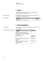
Page 26: ...luorescent lamp Pull out the lamp and replace it Water leaking Leak in a Recirculation Cooling Unit hose Check the hose and tighten the hose clamp Water overflow in the cooling water tank Remove the e...

Page 27: ...ce If possible support the workpiece on both sides Cutting quality differs Cooling water hose clogged Clean the cooling water hose and the cooling tube Check the water flow by turning the cooling valv...

Page 28: ...Replace the cut off wheel The cut off wheel gets caught in the workpiece Support the workpiece and clamp it on both sides of the cut off wheel so that the cut stays open The workpiece breaks when clam...

Page 29: ...s of use Please contact a Struers Service Technician to service the machine The hours counter at the right hand side of Discotom 6 records the number hours that the cutting motor has been in operation...

Page 30: ...e counter on the right hand side of the machine regularly to monitor the actual number of usage hours After lubrication note the date and number of service hours on the Maintenance Log table Move the...

Page 31: ...s are full A bottle with oil for lubricating the slide bearings is supplied with the Discotom 6 When all the oil has been used refill with eg Shell TELLUS oil S100 Check that the O rings are in positi...

Page 32: ...heat Store the cut off wheel in a dry place horizontally on a plane support preferably under light pressure A clean and dry cut off wheel does not corrode Therefore clean and dry the cut off wheel be...

Page 33: ...0x1 5x32mm 9 8 x 0 06 x1 25 Max cutting diameter Max length of cut at a workpiece height of 65mm and width of 205mm The max cutting capacity might be less depending on the workpiece material and the c...

Page 34: ...8A 11 8A Fuse min 20 A 20 A 20 A 20 A 10 A 10 A 10 A max 25 A 25 A 25 A 25 A 20 A 20 A 20 A Residual Current Circuit Breaker type A 30 mA or higher is recommended Safety standards Please refer to the...

Page 35: ...l If AUTO mode is selected de select it Press START Lower the cut off wheel until it contacts the workpiece and apply pressure until the sample is cut Keep the Load Bar in the green or first part of t...

Page 36: ...Discotom 6 Gebrauchsanweisung Handbuch Nr 15677001 Auslieferungsdatum 09 09 2013...

Page 37: ...er Firma Struers ver ffentlichtes Wartungshandbuch darf nur von ausgebildeten Technikern benutzt werden die von Struers dazu berechtigt wurden Das Wartungshandbuch darf nur in Zusammenhang mit dem Ger...

Page 38: ...en Gebrauch einer Absaugvorrichtung weil beim Trennen gef hrliche Gase oder Trennr ckst nde entstehen k nnen 8 Die Gummisch rze auf der linken Seite der Maschine erm glicht es lange berstehende Werkst...

Page 39: ......

Page 40: ...te 8 Stellungen des K hlventils 9 Trennposition 9 Reinigungsposition 9 Leuchtdiode und Warnton 10 Einbau Wechseln der Trennscheibe 11 Werkst ck einspannen 11 Trennvorgang starten stoppen 12 Automatisc...

Page 41: ...sserabfluss 1 R cklaufschlauch 2 m 3 Schlauchschellen 1 Fettspritze f r die Spindel des Y Tisches 1 Fett f r Wartung Schmierung der Welle 1 l f r die Wartung des Trenntisches 1 Satz Gebrauchsanweisung...

Page 42: ...t um Lage und Namen der Teile des Discotom 6 kennenzulernen Trenngriff Schutzhaube mit Fenster Bedienfeld Notstoppschalter Reinigungsschlauch K hlventil Trenntisch Hauptschalter Stundenz hler Verriege...

Page 43: ...f der Seite des Ger tes gibt die zul ssige Netz spannung an Pr fen Sie bitte nach ob diese mit der vorliegenden Spannung bereinstimmt Discotom 6 wird mit elektrischem Anschlu kabel geliefert Bringen S...

Page 44: ...itte Schieben Sie den R cklaufschlauch auf das Winkelrohr und sichern Sie den von der Armierung befreiten Schlauchabschnitt mit einer Rohrschelle Achten Sie darauf dass der R cklaufschlauch nach dem A...

Page 45: ...che Gase oder St ube abgeben Die Absaugvorrichtung reduziert auch die Menge der Kondensation an den Seiten der Schutzhaube Auf der R ckseite des Discotom 6 finden Sie einen Anschlu stutzen f r einen A...

Page 46: ...eduzierte Vorschubgeschwindigkeit R CKW RTS Taste Potentiometer f r Vorschubgeschwindigkeit Lastanzeige Kontrollleuchte f r Notstopp berlastung Kontrollleuchte f r Betriebsart AUTO Auto Netzkontrollle...

Page 47: ...chwindigkeit des Trenntischs Einstellung von 0 1 2 5 mm sec m glich STOP Stoppt die Maschine Die Trennscheibe h rt auf zu rotieren und das K hlwasser flie t nicht mehr VORSCHUB GESCHWINDIG KEIT REDUZI...

Page 48: ...en gestellt Zum Reinigen wird das Ventil gegen den Uhrzeigersinn gedreht so dass der Griff mit der Markierung nach unten zeigt Stellungen des K hlventils Zum K hlen der Trennscheibe drehen Sie den Kno...

Page 49: ...riebszustand AUTO ist die Vorschubgeschwindigkeit zu hoch Die Maschine reduziert die Vorschubgeschwindigkeit automatisch Im Betriebszustand AUTO wurde ein Trennvorgang beendet Die Vorschubgeschwindigk...

Page 50: ...Welle Montieren Sie die neue Trennscheibe Montieren Sie Flansch und Wellenmutter wieder auf ziehen Sie diese sorgf ltig fest Legen Sie das Werkst ck in die Schnellspannvorrichtung und den Anschlag Sch...

Page 51: ...er Trenntisch zur ckgef hrt wird Soll der Trenntisch in die Ausgangslage zur ckkehren dr cken Sie einmal auf die Taste R CKW RTS Beachten Sie bitte da zur Ausf hrung dieses Vorgangs die Schutzhaube ge...

Page 52: ...ngen Sie den Trenntisch mitsamt dem Werkst ck unmittelbar unter die Trennscheibe Schlie en Sie die Schutzhaube Vergewissern Sie sich da die Betriebsart AUTO abgeschalten ist Mit START setzen Sie die M...

Page 53: ...Boden der Trennkammer Drehen Sie das K hlventil auf die Stellung f r Reinigen siehe nebenstehende Skizze Reinigen Sie die Trennkammer gr ndlich Drehen Sie das K hlventil auf die Stellung f r K hlen La...

Page 54: ...mer gr ndlich Bewegen Sie den Trenntisch vor und zur ck um zur gesamten Trennkammer Zugang zu erhalten Reinigen Sie die gesamte L nge der F hrungsschienen mit dem Sp lschlauch und einer B rste um ange...

Page 55: ...n geschw cht wurde oder sichtbare Spuren einer Aufl sung erkennbar sind die durch den Gebrauch einer anderen als der von Struers hergestellten K hlfl ssigkeit verursacht wurden sollte die Haube sofort...

Page 56: ...ren 18 Trennergebnisse optimieren 19 Erl uterung der Sicherheitsvor richtungen 19 2 Zubeh r 20 3 Verbrauchsmaterialien 20 4 Fehlerbeseitigung 21 5 Wartung Stundenz hler 25 Wartung der Trenntische 26 S...

Page 57: ...Trenntisch montieren Der einstellbare Tisch positioniert das Werkst ck rechtwinklig zur Trennscheibe und berdeckt einen Bewegungsbereich von 60 mm siehe Zubeh r Stellen Sie den Trenngriff in die h chs...

Page 58: ...zu schneller Verschlei der Trennscheibe zu vermeiden Verwenden Sie eine geringere Vorschub geschwindigkeit oder eine h rtere Trennscheibe Wie kann die Trennung beschleunigt werden Spannen Sie die Prob...

Page 59: ...rbrauchsmaterialien Siehe Tabelle zur Auswahl der Trennscheiben in der Brosch re f r Trennscheiben Spezifikation Kat Nr Corrozip Umweltfreundliches Zusatzmittel f r K hlwasser Sch tzt die Trennmaschin...

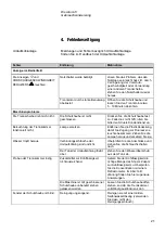
Page 60: ...nktioniert nicht Lampe ersetzen Entfernen Sie die Plastikabdeckung damit Sie Zugang zur Fluoreszenz leuchte bekommen Ziehen Sie die Lampe heraus und ersetzen Sie sie Wasser tropft heraus Verbindungssc...

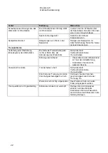
Page 61: ...cheibe pa t nicht zur H rte bzw der Abmessung des Werkst cks Siehe Abschnitt Verbrauchsmaterialien Trennscheiben K hlung unzureichend berpr fen Sie den Wasserstand im Tank der Umlaufk hlung Kontrollie...

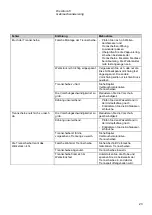
Page 62: ...ren Sie die Vorschub geschwindigkeit K hlung unzureichend Pr fen Sie den Wasserstand in der Umlaufk hlung nach Kontrollieren Sie die K hlwasser schl uche Trennscheibe nutzt sich zu rasch ab Die Vorsch...

Page 63: ...Werkst ck befand sich zu lange in der Trennkammer Nehmen Sie das Werkst ck unmittelbar nach dem Trennen aus der Maschine Wenn Sie von der Maschine weggehen sollten Sie die Schutzhaube zur L ftung offe...

Page 64: ...Wartung des Ger ts wenden Sie sich bitte an einen Struers Serviceingenieur Der Stundenz hler an der rechten Seite des Discotom 6 registriert die Arbeitsstunden des Trennmotors Um ein einwandfreies Ar...

Page 65: ...50 Stunden Pr fen Sie am Z hler an der rechten Seite des Ger ts regelm ig die genaue Zahl der Arbeitsstunden nach Nach dem Abschmieren notieren Sie bitte Datum und Anzahl der Betriebsstunden im Wartun...

Page 66: ...ist l zum Schmieren der Gleitlager wird mit dem Discotom 6 mitgeliefert Ist das l aufgebraucht f llen Sie die Flasche wieder mit Shell TELLUS l S100 Stellen Sie sicher dass die O Ringe in der richtige...

Page 67: ...en Die Trennscheiben sind an einem trockenen Aufbewahrungsort auf horizontaler Unterlage m glichst noch leicht beschwert zu lagern Saubere und trockene Trennscheiben sind ohne Korrosion Deshalb ist es...

Page 68: ...10 x 0 06 x 1 25 Abmessung der Trennkammer Max Trenndurchmeser Max L nge des Schnittes bei einem Werkst ck mit einer H he von 65mm und einer Tiefe von 205mm Die max Trennkapazit t kann abh ngig von Ma...

Page 69: ...1 8A 11 8A Sicherung min 20 A 20 A 20 A 20 A 10 A 10 A 10 A max 25 A 25 A 25 A 25 A 20 A 20 A 20 A Fehlerstrom Schutzschalter Type A 30 mA oder h her wird empfohlen Umgebung Ger uschpegel Etwa 67 dB A...

Page 70: ...Taste START dr cken Trennscheibe absenken bis sie das Werkst ck ber hrt Mit geeigneter Andruckkraft das Werkst ck durchtrennen Lastanzeige im gr nen oder am Anfang des gelben Bereichs halten Zum Ende...

Page 71: ...Discotom 6 Mode d emploi Mode d emploi no 15677001 Date de parution 09 09 2013...

Page 72: ...que pour l quipement Struers pour lequel il a t sp cifiquement r dig Manuels de maintenance Un manuel de service de Struers ne peut tre utilis que par un technicien sp cialiste autoris par Struers Le...

Page 73: ...aiss e lentement et avec pr caution afin d viter une brisure de la meule de tron onnage 7 Struers recommande l utilisation d un dispositif d aspiration car les mat riaux de tron onnage peuvent exhaler...

Page 74: ......

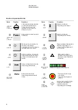
Page 75: ...e Discotom 6 7 Touches du panneau frontal 8 Positions de la soupape de refroidissement 9 Position de tron onnage 9 Position de nettoyage 9 Lampe diode et signaux sonores 10 Monter ou changer la meule...

Page 76: ...u d coulement 2 m 3 Colliers de serrage 1 Graisse de maintenance lubrification de la broche 1 Huile pour la maintenance de la table de tron onnage 1 Seringue avec graisse pour la broche de la table Y...

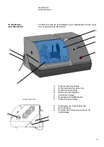
Page 77: ...tom 6 Poign e de tron onnage Ecran de protection avec vitre Pupitre de commande Bouton d arr t d urgence Pistolet de rin age Soupape de refroidissement Table de tron onnage Interrupteur de courant pri...

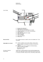
Page 78: ...m de la machine V rifier tout d abord que la tension utilis e correspond la tension indiqu e sur la plaque se trouvant sur le c t de la machine Discotom 6 est l usine quip e d un c ble lectrique Monte...

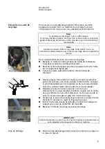
Page 79: ...oup e vers le centre du tuyau Monter le tuyau d coulement sur le tuyau coud et serrer la section d nud e l aide d un collier de serrage V rifier que le tuyau d coulement est inclin vers le bas une foi...

Page 80: ...ant le tron onnage Ce syst me d aspiration permettra galement de r duire le degr de condensation d eau sur les parois de l cran de protection Au dos de Discotom 6 se trouve un joint pr vu pour un tuya...

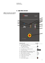
Page 81: ...arche arri re Potentiom tre pour la vitesse d avance Indicateur de charge Lampe indicatrice d arr t d urgence surcharge Lampe indicatrice de mode automatique Auto Lampe indicatrice du courant Power To...

Page 82: ...d avance de la table de tron onnage La vitesse peut tre r gl e de 0 1 2 5 mm sec ARRET Arr te la machine La meule de tron onnage s arr te de tourner et l eau de refroidissement est ferm e VITESSE D A...

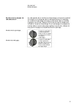
Page 83: ...e de tron onnage Pour le nettoyage la soupape est tourn e dans le sens inverse des aiguilles d une montre marque en bas pour le rin age du compartiment de tron onnage Positions de la soupape de refroi...

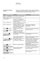
Page 84: ...une de VITESSE D AVANCE REDUITE clignote En mode AUTO la vitesse d avance est trop lev e La machine r duit automatiquement la vitesse d avance Une coupe AUTO est termin e Vitesse d avance r duite R du...

Page 85: ...onter le flasque et le boulon Serrer soigneusement et rel cher le bouton de fermeture Placer la pi ce entre les dispositifs de bridage rapide et la but e au c t gauche de la table de tron onnage Pouss...

Page 86: ...arche La meule de tron onnage se met tourner et l eau de refroidissement est ouverte La table de tron onnage se d place vers l avant en direction de la meule de tron onnage la vitesse d avance program...

Page 87: ...Noter la table de tron onnage peut tre positionn e l aide des touches AVANT et ARRIERE Lorsque les touches sont maintenues press es la table de tron onnage se d place une vitesse accrue de 20 mm sec...

Page 88: ...er et l eau de refroidissement est ouverte Abaisser la poign e de tron onnage et laisser la meule de tron onnage p n trer la pi ce Augmenter la pression et commencer le tron onnage Une fois que la meu...

Page 89: ...de refroidissement en position de nettoyage voir le sch ma de gauche Nettoyer soigneusement le compartiment de tron onnage Noter ne pas nettoyer l cran de protection au tuyau de rin age A la place uti...

Page 90: ...umide Nettoyer soigneusement le compartiment de tron onnage D placer la table de tron onnage d avant en arri re pour avoir acc s au compartiment de tron onnage dans son int gralit Nettoyer les axes de...

Page 91: ...tre imm diatement remplac s il a t affaibli par une collision par des pi ces projet es ou si des signes de d t rioration visibles sont constat s dus l utilisation d un additif de recyclage autre que...

Page 92: ...age 20 Explication des facteurs de s curit 20 2 Accessoires 21 3 Consommables 21 4 Indication d erreurs 22 5 Maintenance Horocompteur 25 Maintenance des tables de tron onnage 26 Lubrifier la table de...

Page 93: ...s D placer la poign e de tron onnage en position sup rieure et la table de tron onnage vers l arri re afin de cr er suffisamment de place pour travailler D placer la partie centrale de la table de tro...

Page 94: ...de tron onnage de s user trop rapidement R duire la vitesse d avance ou utiliser une meule de tron onnage plus dure Comment tron onner plus rapidement Placer la pi ce dans une position permettant la m...

Page 95: ...nsommables Se r f rer au Guide de s lection dans la brochure sur les meules de tron onnage de Struers Sp cification No de cat Corrozip Non nuisible l environnement Pour prot ger la machine de la corro...

Page 96: ...probl me appeler le SAV Struers La lampe du compartiment ne fonctionne pas Remplacer la lampe Retirer le chapeau en plastique pour avoir acc s la lampe fluorescente Tirer sur la lampe pour la faire so...

Page 97: ...vance est trop lev e la fin de l op ration R duire la vitesse d avance vers la fin de l op ration Manque de support de la pi ce Si possible supporter la pi ce des deux c t s La qualit de coupe varie L...

Page 98: ...de tron onnage La meule de tron onnage reste bloqu e dans la pi ce Supporter la pi ce et la brider des deux c t s de la meule de tron onnage afin que la coupe reste ouverte La pi ce se brise lorsqu el...

Page 99: ...eures d utilisation Contacter le SAV Struers pour assurer le service technique de la machine L horocompteur au c t droit de Discotom 6 enregistre le nombre d heures de service du moteur de tron onnage...

Page 100: ...ement le compteur de service sur la droite de la machine afin de surveiller le nombre r el d heures d utilisation Apr s le graissage noter la date et le nombre d heures de service sur le tableau des d...

Page 101: ...lle d huile pour la lubrification des paliers de glissement est fournie avec Discotom 6 Lorsque l int gralit de l huile a t utilis e remplir la bouteille par exemple d huile Shell TELLUS S100 V rifier...

Page 102: ...server la meule de tron onnage dans un endroit sec horizontalement sur un support plan de pr f rence sous une l g re pression Une meule de tron onnage propre et s che ne rouille pas Il faut donc netto...

Page 103: ...de coupe Diam tre de tron onnage max Longueur de coupe max pour une hauteur d objet de 65 mm et une largeur de 205 mm La capacit de tron onnage max peut tre moins importante selon le mat riau et la me...

Page 104: ...11 8A Fusible min 20 A 20 A 20 A 20 A 10 A 10 A 10 A max 25 A 25 A 25 A 25 A 20 A 20 A 20 A Interrupteur de circuit courant r siduel Type A 30 mA ou plus lev est recommand Directives UE Se r f rer la...

Page 105: ...en contact avec la pi ce et appliquer la pression jusqu ce que l chantillon soit tron onn L indicateur de charge doit rester dans la zone verte ou dans la premi re partie de la zone jaune Rel cher la...

Page 106: ...Manual No 15677001 Date of Release 20 Discotom 6 Spare Parts and Diagrams...

Page 107: ...rained technician authorised by Struers The Service Manual may only be used in connection with Struers equipment covered by the Service Manual Struers assumes no responsibility for errors in the manua...

Page 108: ...g wheel guard complete 15110055B Water valve house 15110065H Cover complete 15670030G Lamp complete 15670012C Cabinet complete 15670020B Front plate complete 15670025D Quick Clamping Tool for 10 mm T...

Page 109: ...coil 2MO01623 465 W1 net cable 50Hz 15113501 W1 net cable 60Hz 15113500 470 Red Push Button For Thermal Relay 2SA00301 15670015 Base and back plates complete 0020 Motor 3x200V 50Hz 3x200 240V 60 Hz 2M...

Page 110: ...70050 Cutting spindle complete 10 Spindle shaft 15670110 20 Ball bearing 6007 2RS1 35 62 2BK00110 30 Locking ring J62 DIN 472 2ZL20620 40 O ring 31 42 1 78 NBR70 2IO17829 50 Seal ring 15110158 60 70 S...

Page 111: ...condensator 2CR12301 15670020 Cabinet complete 90 Seal profile 0 76 meter 2IP00205 15670025 Front plate complete 20 Front plate foil 15670400 60 PCB Discotom 6 Contr board 15673380 Accessories Pipe f...

Page 112: ...art list for Discotom 6 Drawing Pos Spare Part Cat no Vertical clamping system for 10 mm T slots TREVS 1 Operating key for TREVS 2GR27021 2 Spring for TREVS 2GR27023 3 Flat clamping shoe 2GR26150 Vert...

Page 113: ...Handle 15870129 110 Excenter Right TENRI 15870190 110 Excenter Left TENLE 15870191 130 Spring 22x3 20 15870161 170 Lube Nipple M6x1 DIN 71412A Zn 2GN90050 180 Rod Seal 25x18x4 35 2IT20060 190 Cap nut...

Page 114: ...C 6 5 2 N 3 4 2 A 5 d F H e b 5 r M o m k k K h n r e r B t i u c r i C l e b a L 0 3 0 1 6 1 0 1 0 0 6 1 e t s r o f r e v o C 4 8 3 0 7 6 5 1 8 1 0 4 0 1 7 0 2 5 0 1 5 0 1 0 5 1 e t a l p t n o r f...

Page 115: ...6 0 0 0 1 A Z 2 0 8 3 2 C M 0 1 5 0 5 R T 2 0 9 3 2 v i k S 5 0 0 0 1 A Z 2 0 1 4 2 C M 0 2 6 0 5 R T 2 0 2 4 1 t n a k 9 5 4 8 2 P I 2 0 3 4 1 t n a K 1 0 0 0 3 P I 2 0 4 4 1 n t t 3 0 2 0 0 P I 2 0...

Page 116: ...n i a m r o f e t a l P 3 0 0 9 1 1 5 1 0 2 6 1 A 6 1 x 4 M e u r k s K M 6 1 4 0 7 R T 2 0 3 6 1 9 4 2 0 6 4 0 0 2 o f a r T 1 1 7 0 7 T M 2 0 4 6 1 W 2 R A B R E P M U J 2 0 4 1 3 L X 2 0 5 6 1 M e...

Page 117: ...l e S P R t s n d e l e S 0 4 0 2 0 3 5 3 0 7 0 5 0 9 1 5 9 1 k t s 6 3 4 2 e t i t c o L d e m s e r k i S n e v r e k t a s d o m 5 0 5 1 1 1 5 1 j t k r v i s e r o b 2 t l a i d a r s e t s a l e...

Page 118: ...1 0 2 0 0 3 7 7 6 5 1 d i t l a e s t e t t e l s r e t o n e g a t n o m l e d n i p S V T J 6 1 8 0 3 1 0 2 V T J V T J t i n I r p p A t i n I w a r D e t a d r p p A D E F C 1 2 3 4 B A 3 2 1 5 C...

Page 119: ...0 1 1 0 2 E P S t i n I r p p A t i n I w a r D e t a d r p p A D E F C 1 2 3 4 B A 3 2 1 5 C D 4 6 7 8 A B t e r e t n o m g n i n m r k s f a e v i k S 5 5 0 0 1 1 5 1 8 6 7 2 O S I S D e c n a r e...

Page 120: ...i l p u o C 3 0 0 0 6 F N 2 0 7 D D 0 6 t d r h r o f s e d n p s e k k i M G P F J M B 7 9 9 1 9 0 8 2 H A t i n I r p p A e t a d r p p A t i n I w a r D n o i t p i r c s e d n o i s i v e R e t a...

Page 121: ...l p r e b b u R 9 6 3 0 7 6 5 1 0 8 1 s r o f e t a l P 8 6 3 0 7 6 5 1 0 9 8 r t e o m p o T 0 4 0 0 3 A T 2 0 0 1 1 r p g n i l a e S 1 9 3 0 7 6 5 1 5 0 1 6 u r k s R H U 5 0 3 0 3 R T 2 0 1 1 2 p...

Page 122: ...e t a d a e r C n o i t p i r c s e d n o i s i v e R A C 5 2 0 1 4 0 0 2 5 1 6 0 1 1 0 2 d e d d a s w e r c S E J C 5 2 0 1 4 0 0 2 J M B E P S t i n I r p p A t i n I w a r D e t a d r p p A D E F...

Page 123: ...EOHG Material Scale ID Format Revision Crea date Revision description Draw Init Appr date Appr Init Rev Pederstrupvej 84 DK 2750 Ballerup Copenhagen Denmark Phone 45 44 600 800 Fax 45 44 600 804 A B C...

Page 124: ...1 0 2 1 0 3 1 n o i s i v e R e t a d a e r C n o i t p i r c s e d n o i s i v e R A D 6 0 8 0 4 0 0 2 6 1 6 0 1 1 0 2 s e g n a h c o n d e t a d p u g n i w a r D J M B 6 1 6 0 1 1 0 2 E P S t i n...

Page 125: ...2 0 4 2 0 5 2 0 6 2 0 7 2 0 8 2 0 9 2 0 0 3 2 0 3 0 5 1 0 5 1 7 8 5 1 w a j d n a d o r n g i l a o t l o o t g n i t n u o m e s U 0 3 0 3 d e l b m e s s a s t i r e t f a h s i l o P l e e t s s s...

Page 126: ...i l b m e s s a r o f d e s u 2 6 0 5 1 7 8 5 1 0 0 2 A A t n e m e v o m d o r y s a e r o f t s u j d A 0 3 2 d e l b m e s s a s t i r e t f a h s i l o P l e e t s s s e l n i a t S n e v i g e b...

Page 127: ...p i r c s e d n o i s i v e R e t a d a e r C v e R 5 1 1 0 0 1 0 2 V T J Y R B 5 1 1 0 0 1 0 2 t S d r a H t S l n i a t S d e g n a h c l a i r e t a M 0 2 s o P 6 0 5 0 5 0 2 3 1 4 F E D A B C y s...

Page 128: ......

Page 129: ......

Page 130: ......

Page 131: ...es Only if S1 current values is not available use voltage variant column to decide correct switch settings RD4 RD31 RD11 Rev B FTH 30 03 2005 Emergency Stop moved New PCB Always only 1 winding in T2 S...

Page 132: ...k M YS1 0 V 200 V Safety Trafo IEC 60742 UL CSA Supervision 3 ph motor 140 C Thermoswitch Cutting Motor M4 2 2 Connector for External Recirculation Unit Activation of M1 brake function Activation of M...

Page 133: ...kling og Produktion Struers A S English Declaration of Conformity Manufacturer Struers A S Pederstrupvej 84 DK 2750 Ballerup Denmark Telephone 45 44 600 800 Herewith declares that Product Name Discoto...

Page 134: ...Skjold Heyde Stellvertretender Gesch ftsf hrer Entwicklung und Produktion Struers A S Fran ais D claration de conformit Fabricant Struers A S Pederstrupvej 84 DK 2750 Ballerup Denmark T l phone 45 44...

Page 135: ...m Magnutom 400 500 PETG thickness Front 10mm Side 8mm The safety hoods window primary function is to protect against samples not clamped properly The safety hood is made from PETG which is generally u...

Page 136: ...0mm Seite 8mm Die prim re Funktion der Sicherheitshaube scheibe ist der Schutz vor Proben die nicht korrekt eingespannt sind Die Sicherheitshaube ist aus PETG hergestellt das generell f r alle Struers...

Page 137: ...8mm La fonction premi re des crans vitres de s curit est d assurer une protection contre les chantillons qui n ont pas t correctement brid s L cran de s curit est fabriqu en PETG g n ralement utilis...

Page 138: ...cutting ta ble with the clamped workpiece will move forward towards the cut off wheel at the set feed speed Before cutting you can of course position the cut off wheel to compensate for the wear of th...

Page 139: ...hows the cutting capacity in automatic cutting mode with a new cut off wheel and exible clamping tools The real cutting capacity depends on the sample material Automatic Feed Speed Reduction When cutt...

Page 140: ...ing chamber allowing you to monitor the cutting process through the large window in the protection guard An exhaust sys tem may be connected Quick and Handy Clamping of the Workpiece The integrated cu...

Page 141: ...40 mm x 225 mm A wide range of cut off wheels is available for Discotom 6 Please refer to the separate brochure 12 2012 62110567 Printed in Denmark by Rosendahls Struers A S Pederstrupvej 84 DK 2750 B...

Page 142: ...st ck mit voreingestellter Vorschubgeschwin digkeit auf die Trennscheibe zu Selbstverst ndlich kann die Trenn scheibe vor dem Trennvorgang so po sitioniert werden da der Verschlei der Trennscheibe ber...

Page 143: ...ur ck f hrt Automatische Reduktion der Vorschubgeschwindigkeit Trennkapazit t H chster trennbarer Durchmesser 80 mm Tiefe mm H he mm Das Diagramm zeigt die Trennkapazit t in automatischer Betriebsart...

Page 144: ...euchtet die Trennkammer gut aus und erm glicht es den Trenn vorgang durch das gro e Fenster in der Schutzhaube zu berwachen Ein Absaugsystem ist anschlie bar Rasches und praktisches Einspannen der Wer...

Page 145: ...1 8188 info struers com Alle Struers Produkte werden laufend weiter entwickelt Wir behalten uns deshalb das Recht vor nderungen unserer Produkte ohne vorherige Ank ndigung vorzunehmen Technische Daten...

Page 146: ...meule de tron onnage la vitesse d avance pr programm e Avant de proc der au tron onnage il est bien s r possible de positionner la meule Discotom 6 Machine de tron onnage universelle la fois automatiq...

Page 147: ...ue illustre la capacit de tron onnage en mode automatique avec une meule de tron onnage neuve et des outils de serrage exibles La capacit de coupe r elle d pend du mat riau Capacit de tron onnage diam...

Page 148: ...i vous permettra de surveiller le pro cessus de tron onnage par une large vitre dans l cran de protection Un syst me d a ration peut y tre bran ch Serrage rapide et facile de la pi ce La table de tron...

Page 149: ...Puissance maximum 4 4 6 0 kW 6 0 8 0 HP Meules de tron onnage Taille de meule de tron onnage 250 mm x 1 5 mm x 32 mm Vitesse de rotation en marche vide 2850 t m 50 Hz 3420 t m 60 Hz Table de tron onn...

Reviews: