background image

EARTH MOVING

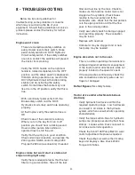
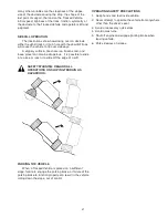
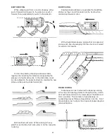
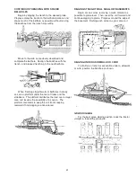
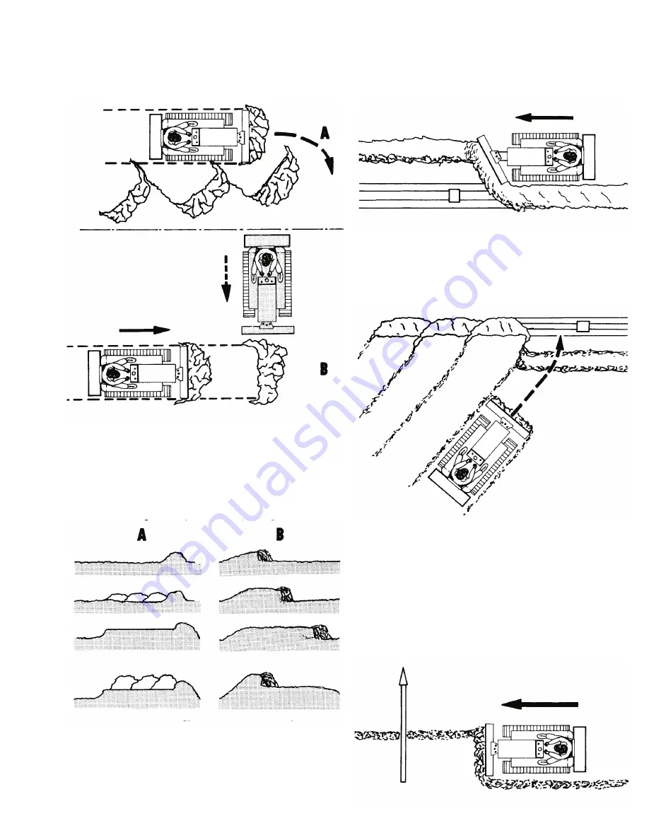
When stripping soil from a road or driveway, either

push it forward and angle it to the side (A) or push it
forward, then perpendicularly push it to the side (B).

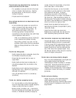
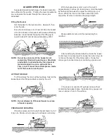
Dirt can be piled by dropping successive loads

together, then leveling this material and repeating the
process at a higher plane (A). In the alternative, loads
can be dumped in the opposite direction, creating the new
plateau while pushing loads forward (B).

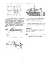
Both methods will work. When working in heavy

growth or particularly hard soils, plow or rip the area prior
to dozing.

BACKFILLING

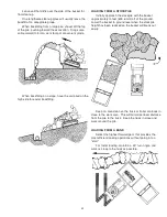
Angling blade bulldozers are excellent for backfilling

ditches as they can drift material into the trench while
maintaining forward motion.

With straight blade dozers, approach at an angle and

end up each pass by swinging into the structure or culvert
for smooth, fast results.

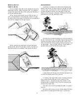
FINISH DOZING

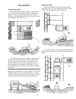
Side slopes can be finished with a dozer by starting

at the top and traveling parallel to the right-of-way. Earth
from each pass will fall to the lower side of the blade and
form a windrow. This material is then picked up on
succeeding passes filling up irregularities in terrain. Don’t
allow blade corner to dig as the slope will steepen beyond
job specifications.

44

Summary of Contents for MAGNATRAC MH8000

Page 1: ...MH8000 COMPACT CRAWLER Version 8 12 Copyright 2012 C F Struck Corp All rights reserved ...

Page 2: ...opera tion safety basic mechanical construction and proper maintenance All the information you need is in the following Operator Manual Take time NOW before you start to operate your Magnatrac to go over the complete Manual Read in detail the operating and safety instruc tions Read for background other sections such as lubrication service etc you can go back later for more detailed reading when yo...

Page 3: ...e run all day submerged in mud or it may be monthly or quarterly maintenance because your tractor is working in a relatively clean environment like grass 4 Grease is good Consistent lubrication of all moving joints like all pins and cylinders will greatly extend the life of your equipment with one exception The 4007 1090 Drive Chains should not be lubricated with a thick or sticky lubricant like g...

Page 4: ... is to apply your Parking Emergency Brake This is an over ride braking action used to augment the hydraulic system s dynamic braking effect Again to protect your drive system from harmful shock loads the brakes like the Track Controls must be applied with controlled force never in a snapping action SUMMARY Your crawler should always be operated with forethought rather than in a series of sudden an...

Page 5: ...achments in certain industrial type applications may affect Warranty cover age D RETURNS AND REFUNDS In the event of defective materials or workmanship the purchaser agrees to allow C F Struck Corp the opportu nity to correct the defect in a timely manner at the expense of C F Struck Corp It is at the discretion of C F Struck Corp to either correct the defect or refund the purchaser To return a St...

Page 6: ...iodic Service Chart 14 7 SERVICE 16 Engine 16 Starter 16 Battery 16 000441 Interlock Switches 17 Safety Circuit Test 18 Seat Weight Adjustment 18 Drive Chain Tensioning 19 Parking Emergency Brake 20 Track Maintenance 21 Sprocket Idler Lubrication 25 Track Idler Maintenance 25 Track Shoes 26 Belt Tensioning Replacement MH7000 only 26 8 TROUBLE SHOOTING 28 9 OPERATING TIPS PROCEDURES 30 10 PART IDEN...

Page 7: ... Crawler s forward travel Record your Crawler serial model numbers in the spaces below You need this information when you order parts or require technical support Crawler Records Model __________________________________________ Crawler Serial ________________________________ Engine Brand __________________________________ Engine Serial ________________________________ Backhoe Serial ______________...

Page 8: ...___ ________ _____________________________________________ ________ _____________________________________________ Date Service Work ________ _____________________________________________ ________ _____________________________________________ ________ _____________________________________________ ________ _____________________________________________ ________ _______________________________________...

Page 9: ...pment Drive at safe speeds at all times especially on rough ground and hillsides Carry the Bucket or Blade as low as possible at all times especially when you work on a hillside or back up a steep hill Do not lower a loaded Bucket or Fork with the control lever in float position Do not drive too close to the edge of a ditch or excavation Watch for overhead wires Do not touch wires with any part of...

Page 10: ...Engine while working on the Crawler Be careful when handling any type of fuel Do not smoke while filling the fuel tank or working on the fuel system Check for faulty wiring or loose connections Do not lubricate or work on the Crawler while it is moving Release hydraulic pressure before working on hydraulic system Move every hydraulic control lever back forth until equipment does not move Before us...

Page 11: ...s and nozzles which eject fluids under high pressure Use a piece of cardboard or paper to search for leaks Do not use your hand If ANY fluid is injected into the skin it must be surgically removed within a few hours by a doctor familiar with this type of injury or gangrene may result INSTALL AND MAINTAIN ROPS PROPERLY If Roll Over P r o t e c t i v e Equipment is loosened or removed for any reason...

Page 12: ... RELEASE HANDLE E CHOKE CONTROL F HAND THROTTLE CONTROL G FOOT THROTTLE CONTROL H LIGHT SWITCH I SEAT SAFETY SWITCH J IGNITION SWITCH K OVERDRIVE ACCESSORY CONTROL L FAN SWITCH M HOUR METER N HYDRAULIC OIL TEMPERATURE O AMMETER P HYDRAULIC CIRCUIT CONTROL Q HYDRAULIC TANK BREATHER FILLER R UNLEADED GASOLINE TANK 6 MH8000 Controls Instruments A B Q C D K E F J M R P N O M I L H G Verson 8 24 12 ...

Page 13: ...aight rearward pull both Left and Right Track Controls rearward 3 To turn right push forward on Left Track Control 4 To turn left push forward on Right Track Control 5 To counter rotate Tracks shortest turn possible push one Track Control forward while simultaneously pulling rearward on the other Track Control NOTE When either Track Control lever is released it will automatically return to neutral...

Page 14: ...S An auxiliary bank of Control Valves is located to the operator s right These valves are used to control all attachments on your tractor Your MH8000 crawler will contain from one to five of these valves based on the attachments you have K OVERDRIVE ACCESSORY CONTROL This Overdrive Accessory Control Valve has two functions 1 When pushed fully forward and locked into the Overdrive position this val...

Page 15: ... Drive Pump Monitor this temperature so that it does not exceed 180 degrees Fahrenheit If the oil temperature exceeds 180 degrees stop operating the Crawler but allow the Engine to operate at medium speed to circulate the oil through the oil cooler and lower its temperature O AMMETER Measures electrical charge or discharge to battery If Ammeter shows a discharge shut down electrical system by turn...

Page 16: ...ness and condition BATTERY COMPARTMENT Remove trash Check cables for tightness and corrosion FUEL TANK Check fuel level HYDRAULIC SYSTEM Check for leaking lines and connections Check for bent or kinked lines Check for lines rubbing against each other or against other parts Check oil level OPERATOR S STATION Check levers for free movement Check ROPS and Seat Belt Clean floor and instrument panel Ad...

Page 17: ...e stop before attempting to restart the Engine If the starter is engaged while the flywheel is rotating the starter pinion and flywheel ring gear may clash resulting in damage to the starter If the starter does not turn the Engine over shut off starter immediately Do not make further attempts to start the Engine until the condition is corrected If the battery charge is not sufficient to turn over ...

Page 18: ... 4 Run Engine at half speed 2 minutes without load 5 Move Throttle Control to slow idle 6 Turn Ignition Switch to Off 7 Release hydraulic pressure by rocking all hydraulic controls back and forth IMPORTANT If Engine stops under load remove load Start Engine immediately Run 30 seconds at half speed before adding load NOTE If engine stops you must turn key Off before you can start the engine IMPORTA...

Page 19: ...ir sides with plugs up IMPORTANT Keep all dirt scale water or other foreign matter out of fuel LUBRICANTS ENGINE OIL Check enclosed Engine Owner s Manual and closely follow their recommendations HYDRAULIC OIL Use a premium quality hydraulic oil with maximum anti wear properties rust and oxidation treatment A high quality antiwear hydraulic fluid designed for use in high pressure high speed hydraul...

Page 20: ...GI 2 Grade Lithium Complex ISO VG 220 A small breakdown of how many grease fittings are on each MH8000 tractor and various Attachments is as follows MH8000 14 For an MH8000 all grease fittings will be on the outside of every Axle Pin except for the Front Idler axle On the Front Idler axle it is on the inside end of the welded tube Hint You may have to rotate the tracks to find these grease fitting...

Page 21: ... is for the front axle to be square In addition check that the 235 Washer against the front face of each 215 Front Axle is not loose enough to be rotated with fingers Check Service section of this manual for complete explanation and Track tensioning procedures See Drawing MH B and Photo MH 13 Drive Chain Lubricating Oil the 4007 60 Drive Chain and also the 1090 80 Drive chain as well Working the o...

Page 22: ...ct with skin eyes and clothes When you work around batteries protect eyes and face from battery fluid and explosion Antidotes for Sulfuric Acid EXTERNAL 1 Flush skin well with water 2 Flush eyes for 15 minutes 3 Get medical attention immediately INTERNAL 1 Drink a large amount of water or milk 2 Then drink milk of magnesia beaten eggs or vegetable oil 3 Get medical attention immediately CAUTION Ke...

Page 23: ... to the terminals of the Switch should have its light on at this time B With the 4039 I Treadle released and allowed to rise to the height permitted by the two restraining Cap Screws the Switch should be open the light should be off If both of the above conditions are not met you must adjust the height of the 441 Seat Switch The Switch is secured top and bottom of the 4027 Seat Plate with large he...

Page 24: ...Conduct the following tests to check proper functioning of Safety Circuit related switches A Following recommended safe starting procedures and with operator seated but Parking Brake not applied attempt to start Engine The Engine should not start If it does readjust 441 Switch on 539C Bracket Switch is mounted too high in its Bracket and is closing too soon If readjustment doesn t solve the proble...

Page 25: ...you must move 223 Shaft up to remove slack in Chain Loosen two 1 2 Machine Bolts 232 SHIMS Reference Photo for DRIVE CHAIN TENSIONING 4007 1090 Chains page 21 Loosen Three 3 3 8 Carriage Bolts on left right side of 4001 Motor Box tighten securely after your Chain adjustment Only If Necessary Loosen two 1 2 Cap Screws holding front end of 4001 Motor Box tighten securely after your Chain adjustment ...

Page 26: ...slack in Chain To Tighten 1090 Chain you must move 214 Axle down to remove slack in Chain Only If Necessary Loosen two 1 2 Cap Screws holding front end of 4001 Motor Box tighten securely after your Chain adjustment Loosen Three 3 3 8 Carriage Bolts on left right side of 4001 Motor Box tighten securely after your Chain adjustment Reference Photo for DRIVE CHAIN TENSIONING 4007 1090 Chains page 21 ...

Page 27: ...ighten the two 3 8 Bolts holding the 249 Support to the frame Replace 4025 Pan electrical plug on Seat Switch and then start and operate Crawler Check Drive Chain adjustment and readjust if necessary Tighten 1090 Drive Chain 80 roller chain by increasing the center distance between the movable 214 Rear Axle and the fixed 436 Shaft do this to both sides of Crawler Consult the two reference photos a...

Page 28: ...ss the Track Drive Controls are released immediately The Brake s other use is that of an Emergency Brake If you should ever lose Engine or drive system power the Brake can be activated instantly to hold the Crawler safely in position DISK BRAKE ADJUSTMENT CAUTION Read the following Disk Brake and Disk Puck instructions in their entirety before attempting any Disk Brake adjustments Consult the part...

Page 29: ...epeating the DISK BRAKE ADJUSTMENT steps detailed above Check with factory Service Department with any questions you may have regarding when and how to replace Brake Pucks brake linings or other brake related parts TRACK MAINTENANCE Before attempting to complete any of the three parts of this Track Maintenance section it is recommended that you read all three parts completely to provide background...

Page 30: ...ective Inner Outer Sprockets See Drawing below To ease Track rotation insert the 1521 Lever Rod shipped with your MH8000 between two Track Plates and fully engage the Rod s end on the bottom of the tube of the 1228 Front Idler NOTE Insert the 1521 Lever Rod between Track Plates located at about the 1 00 o clock position and rotate Lever Rod downward CAUTION Remember to periodically rock the Track ...

Page 31: ...ever Rod on the Rear Drive rotate the Track forward while working the Track s Inner Chain up over the Front Idler s Outer Sprocket NOTE The above step is probably the most difficult because the end of the Track you are working with is extremely heavy and except for your own lifting efforts is totally unsupported Here is where your helper can be of assistance by using the Lever Rod or suitable crow...

Page 32: ...30 Rod clockwise draw the 1 2 Nut 235 Washer on each Rod s end against its respective 233 or 234 spring A set of pneumatic air tools will greatly aid in this process The original factory measurement of the black outside 234 Spring is 4 5 inches The inside spring 233 will NOT be the same measurement Don t include the washers with this measurement The most important thing is for the Front Axle to be...

Page 33: ...xle forward to the rear face of the frame block should be equal on each end of the 215 Axle you are adjusting To accomplish this loosen the 1 2 Nut on the end of the 1030 Rod holding the 233 Spring yellow and fine tune the overall length of the 233 Spring using the procedure described above When equal Y distances have been achieved replace and tighten the 1 2 Nut on extreme end of 1030 Rod holding...

Page 34: ...anges of the 1218 idlers will continue to wear over time Individual idlers should be replaced when track chains begin wearing into the tube connecting the flanges TRACK SHOES Your Crawler comes from the factory without any Track Shoes being installed unless you had the factory install them for a fee You can safely run your Crawler without Track Shoes but under average soil conditions you will be a...

Page 35: ...3 Cover by removing the two bolts securing it to the 1382 Pump Mount NOTE Spacer Tubes are located over these two bolts between the 1383 Cover and 1382 Pump Mount Take care not to lose these Spacer Tubes during removal 4 Loosen but not remove the four 3 8 Bolts securing the 1382 Pump Mount to the Engine 5 To replace the 1361 Belt slide the 1382 Pump Mount to the left until belt tension is relieved...

Page 36: ...h 294 wire connectors if needed Engine cranks but won t start or starts and stops running right away Verify there is adequate fuel that the fuel filter is in good condition Take off the fuel filter and fuel line by the tank Check to make sure the fuel line and or tank is not clogged with any debris Check hoses leading to the fuel pump and to the carburetor Also check that the fuel petcock is in th...

Page 37: ... broken or shattered resulting in popping noises Check for stuck items in the track chain like rocks or other debris Verify the track tension on the front idler sprockets is evenly adjusted on the inside and outside of the track Unequal tensioning can result in the front idler sprocket running at an angle not parallel to the track line See the Service section of this manual This results in tracks ...

Page 38: ...to pull the tractor from the front hold the drive handles forward so the hydraulic oil flow will open up the correct ports to do so In a similar manner if you d like to pull the tractor in reverse hold the drive handles down in the rear position This lets the oil flow in the correct direction for emergency movement ONLY Oil is overflowing from the hydraulic tank or front pump belt keeps breaking C...

Page 39: ...afe and efficient work procedures for a compact crawler tractor equipped with standard attachments loaders backhoes blades etc Each crawler operator encounters dramatically different working conditions than another For this reason the following drawings and descriptions are general in nature They illustrate general points rather than details which may apply to only one operator s working condition...

Page 40: ...ill hit bottom when the wheels on either end are driven over a drop off In most cases this will stop vehicle motion and give immediate warning A tracked Vehicle however will continue on without any warning until its center of gravity passes across an imaginary line drawn straight up from the furthermost point of support with ground It will drop SUDDENLY See illustration upper right THIS WILL HAPPE...

Page 41: ...AIN Vehicle stability on a hill for example is determined not only by the general slope of the hill but also by terrain conditions rocks ditches logs drop offs etc and by the nature of the hill surface gravel sand grass snow rock etc the payload which the vehicle is carrying the manner in which the payload is distributed within the vehicle attachments and accessories which have been added to the v...

Page 42: ...MALLER OBSTACLES WILL CAUSE A TRACKED VEHICLE TO TIP OVER SAFETY WANING OBSTACLES SOME OF WHICH MIGHT BE DRIVEN OVER SAFELY WHILE ON LEVEL TERRAIN CAN CAUSE A HAZARD WHILE OPERATING ON SLOPES DROPOFFS This illustration is drawn to depict a dropoff situation in which a Tracked Vehicle can be expected to flip Variations occurring in natural terrain the approach to the obstacle operator skill and loa...

Page 43: ...d and loose gravel can also be dangerous It is possible to slide into a tree or rock or to slide off the edge of a cliff SAFETY WARNING REGARD ALL OPERATIONS ON SLOPING TERRAIN AS HAZARDOUS PARKING THE VEHICLE When a Tracked Vehicle is parked on a sufficient slope failure to engage the parking brake or failure of the parking brake to function properly can result in the vehicle rolling down the slo...

Page 44: ...rry the load without spillage fully roll the bucket back after filling and before moving the unit NOTE Do not attempt to lift bucket loads in excess of loader capacity PEELING AND SCRAPING USe down pressure and a slight bucket angle to start long cuts Make a short angle cut and break out cleanly With the bucket level start a cut at the notch approximately 2 inches 50 8 mm deep Hold the depth by fe...

Page 45: ...he load keep the bucket as low as possible to resist tipping in case a track drops in a rut DUMPING THE BUCKET Lift the bucket high enough to clear the side of the vehicle Move unit in as close to the side of the vehicle as possible then dump the bucket After the bucket is dumped back away from the vehicle while lowering and leveling the bucket BACKFILLING Efficient backfilling occurs by pushing m...

Page 46: ...ILE Initially approach the stockpile with the bucket approximately to feet 609 6 mm off of the ground Lower the bucket to ground level when the stockpile height has been reduced so the bucket will break out easily Keep an area clean so the truck or trailer can back in close to the work area This will minimize travel distance from the pile to the truck Keep the truck in close and work around the pi...

Page 47: ...e banks as low as possible for maximum efficiency Remember that loader lift and break away capacities diminish rapidly as loading height is increased BREAKING AND SPREADING LARGE PILES Side cutting is a good technique for cutting down a large stockpile If the pile sides are too high and are likely to cave in use the loader to break them down Then build a ramp by shovel loading material from the to...

Page 48: ...ls where they will be used If soil is excessively hard loosen it with a ripper or plow The remaining ramp can be cut out with either a backhoe or by hand When regular loading tools are not available it is possible to utilize bulldozers for filling tracks and trailer Inclined ramps built of earth steel or wood are a means to assist loading economically when level terrain predominates DOZER DITCHING...

Page 49: ...material over the side of the cut 9 D 2 Working from Side only A short wide shelf may also be cut in a hillside working from the side only as illustrated below The first cut A is made parallel to the hillside followed by a second cut B in which the tractor s inside track rides in the trough formed by the previous cut This tilts the tractor to a more level position depending on depth of trough and ...

Page 50: ...low or rip the area prior to dozing BACKFILLING Angling blade bulldozers are excellent for backfilling ditches as they can drift material into the trench while maintaining forward motion With straight blade dozers approach at an angle and end up each pass by swinging into the structure or culvert for smooth fast results FINISH DOZING Side slopes can be finished with a dozer by starting at the top ...

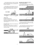
Page 51: ...rators Always have a plan of operation When dropping down a steep hill or over the side of a fill use blade for a brake When traveling carry the blade low This practice helps protect drivetrain and other vital parts of the tractor If possible slot doze to keep load from spilling around the sides of the blade TECHNIQUES FOR COMPLETING VARIOUS PROPERTY IMPROVEMENTS When enlarging ponds or streams le...

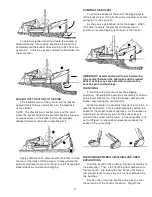
Page 52: ...ht can balance Effective counterweight is the weight of the tractor from the stabilizer pads to the loader Set the stabilizers to remove weight from the rear track wheels The tracks are to remain touching the ground as this provides for the widest stabilizer stance and the lowest center of gravity Raising the tracks off the ground will not only reduce stability and digging depth but will impair pe...

Page 53: ...ucket is empty the dipstick and bucket are in position to resume digging upon return to the trench IMPORTANT Avoid constant jarring or hammering type contact between the spoil pile and the loaded bucket as this may cause premature wear to the backhoe pins and bushings TRENCHING Trenching is the most basic backhoe digging operation Other digging operations are merely variations of this basic functi...

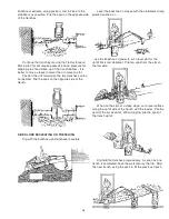
Page 54: ...trench SIDE SLOPE EXCAVATING OR TRENCHING Dig with the backhoe uphill whenever possible Level the backhoe on slopes with the stabilizers to dig plumb trenches or use the backhoe or loader to cut a level slot for the uphill track and stabilizer Pile ten spoil from the slot on the low side When on the side of a steep slope cut a level surface along the uphill side of the trench with the loader Pile ...

Page 55: ... and the stabilizers The platform distributes the load over a larger area and lessens the possibility of a cave in The platform also tends to keep the unit from creeping rearward if hard digging is encountered DIGGING STRAIGHT WALL SHALLOW BASEMENTS Begin at one corner removing a much material as possible to grade level Then reset the unit forward and continue digging to grade Progress around the ...

Page 56: ...the close end wall PIPELINE LEAK REPAIR Locate the pipeline with a bellhole about six feet 182 cm wide and tenn feet 304 cm long Then dig lengthwise along the pipeline to locate the leak When the leak is located position the unit to dig at grade level on both sides of the pipeline If a length of pipe must be replaced strip the soil form both ends of the bellhole Dig the bellhole or trench large en...

Page 57: ... backing up may be necessary to clear the blade so it can always cut cleanly Otherwise the blade will slide over root and accomplish little Heavier trees and brush require more car and time to uproot First contact tree with blade high and centered for maximum leverage Make contact gently push a few times at half throttle while watching the top carefully Look for dead limbs they re widow makers If ...

Page 58: ...time Track spinning is wasted effort TRANSPLANTING When transplanting trees of suitable size place bucket under the dirt ball and lift it to a new site securing the trunk to the bucket When the tree is too large to lift in a bucket dig around the tree as previously described and then push it over the ground to its new destination Note below LOGGING When pulling timber or poles the front end should...

Page 59: ... doesn t move something is holding it Before proceeding find cause and remedy it to prevent machine damage Many rocks such as shale and sandstone are found in tipped position Always dig under the outcrop lift and break it out rather than try to penetrate from the opposite side Sometimes driving a tractor on top will crush such rocks making removal easy STUMPS Small dozers can tackle big stumps if ...

Page 60: ...ssembly Right 1 000229L Cover Left 1 000229R Cover Right 1 000232sfp Shim 25 000232sfp Shim 24 000233 Spring front axle inside yellow 2 000234 Spring front axle Outside Black Green 2 000235sfp Washer spring notched 1 9 16 OD x 7 16 ID 16 000240 O Ring 1 1 8 OD x 7 8 ID 60 000242 Washer Steel 1 1 2 OD x 7 8 ID x 18 gauge 90 000243A Shell 8 000243B Bearing 1 1 4 ID Set Screw 4 000244 Pin spring 1 4 ...

Page 61: ...1 000504sfp Seat Pin 1 000506 Spring Compression 2 000515 Hose Assembly 1 x 14 1 000524LXX Left Motor Assembly 1 000524 Track Motor 1 000523 Fitting 1 004003 004003 Torque Arm painted 1 000527 Fitting Straight 848 FSO 10x10 1 BOLT 1 2 32 1 2 13 X 1 1 4 G5 BOLT 2 NUT 1 2 244 1 2 13 DOT LOCK NUT 2 WASH 1 2 264 1 2 FLAT WASHER 2 000524RXX Right Motor Assembly 1 000524 Track Motor 1 000522 Fitting Bar...

Page 62: ...4 000873 Roll Pin 2 000874 Key 2 000904 Foot Pad Non skid 7 000932 Hose Clamp 1 6 000936 Hose Clamp 28024 2 001030sfp Rod replaces 820 4 001041E Standard Valve Section 1 001041xx Attachment loader valve 1 001041 4 bank Salami Attachment Valve 1 000908 O Ring Plug 3 4 16 721 FSO 08 4 000790 Straight Fitting 848 FSO 06X08 4 000792 Fitting 849 FSO 08 10 2 000611 Fitting 45 deg swivel 889 FS 08 1 0010...

Page 63: ...le 1 001364 Rubber Hood Latch 4 001375 Plate 1 001378 Box 1 001385sfp Tube 2 001389 Headlight 2 001442 Spring MB 3102 1 001454 1 1 4 90 Degree Elbow 1 001456 Elbow 3 4 45 Degree Male 1 001461 Instrumental panel for upper frame 1 001466 Swivel Tee 871 FS 10 1 001470 Fitting 848 FS 08x08 1 001479 Hose 1 in soft x 8 1 2 in lng 1 001480 Hose 1 in soft x 16 1 2 in 1 001481 Hose 1 1 4 soft x 8 in lng 1 ...

Page 64: ... 004009L Front fender support left painted 1 004009R 004009R Front Fender Support right painted 1 004011L 004011L Left Fender painted 1 004011R 004011 Right Fender painted 1 004012 004012 Siffener painted 1 004013 004013 Valve Angle 1 004014 004014 Valve mount plate painted 1 004015L 004015L Left side panel painted 1 004015R 004015R Right side panel painted 1 004016xx 004016xx Oil cooler assembly ...

Page 65: ...ide Panel 1 004050 4050 hose 1 2 x 15 w 1 08 and 1 10 1 004051 4051 hose 1 2 x 11 1 08 x 1 10 1 004052 4052 hose 1 2 x 27 3 4 2 10 s 1 004053 4053 hose 1 2 x 22 1 4 2 10 s 1 004054 4054 hose 1 2 x 55 1 08 and 1 10 1 004055 4055 hose 1 2 x 82 2 08 s 1 004056 004056 hose 1 2 x 72 2 08 s 1 004057 004057 hose 1 2 x 35 2 10 s 1 004058 004058 hose 1 2 x 9 1 2 1 004059 004059 rivet 1 8 x 5 8 4 004061 Par...

Page 66: ...ey 1 4 x 1 4 x 1 pulley 1 000235sfp Washer spring notched 1 9 16 OD x 7 16 ID 8 000792 Fitting 849 FSO 08 10 1 000851 Fitting 90 deg 849 FSO 10X10 1 001039 Fitting metric oil drain 14MM 6MJ 1 001355 Pump 3 4 shaft 1 001356 Hub 1 001359 Pulley 1 1 8 x 5 1 001360 Pulley 5 8 x 5 1 001361 BX27 Belt 1 001363B Heat shield for 31 35hp Briggs 1 001363C Muffler for 31 35hp Briggs 843741 1 001372 Torque Arm...

Page 67: ...ZC 38 BOLT 3 8 88 3 8 16X1 1 4 CARR BLT ZC 4 BOLT 5 16 11 5 16 18 X 2 1 2 G5 BOLT 4 BOLT 5 16 121 5 16 18X3 4 SPIN LOCK BLT 56 BOLT 5 16 121 5 16 18X3 4 SPIN LOCK BLT 2 BOLT 5 16 121 5 16 18X3 4 SPIN LOCK BLT 41 BOLT 5 16 124 5 16 18X1 1 4 HX SPIN LOCK BLT 2 BOLT 5 16 125 5 16 18X1 1 2 HX SPIN LOCK BLT 4 BOLT 5 16 14 5 16 18 X 4 G5 BOLT 2 BOLT 5 16 19 5 16 18 X 1 2 G5 BOLT 4 BOLT 5 16 19 5 16 18 X...

Page 68: ...8 SPIN LOCK NUT 80 NUT 5 16 231 5 16 18 SPIN LOCK NUT 32 NUT 5 8 245 5 8 11 DOT LOCK NUT 4 NUT 8 32 218 8 32 NYLON LOCK NUT 8 SETSCW 1 4 177 1 4 28X3 8 SET SCREW 4 SETSCW 3 8 174 3 8 16X1 2 SET SCREW 2 SETSCW 5 16 178 5 16 24X1 2 SET SCREW 2 WASH 1 2 264 1 2 FLAT WASHER 8 WASH 3 8 262 3 8 FLAT WASHER 4 WASH 3 8 262 3 8 FLAT WASHER 4 WASH 3 8 282 3 8 Star Washer 4 WASH 3 8 286 3 8 X 1 1 2 FEND WASH...

Page 69: ...partment Behind Dash MH 9 Top Rear View Track Drive Motors 60 Top Drive Chain MH 10 Front View Belt Adjustment MH 11 Top Rear View Track Drive Motors close up MH 12 Right Front View Front Idler Outside Spring MH 13 Right Side View Track Adjustment Spring Outside MH 14 Top View of Right Motor Box MH 15 60 Chain Adjustment Disk Brake MH 16 Inside View of Right Motor Box MH 17 Lower Frame View 60 80 ...

Reviews: