Page 9 of 22
Testing and Operational Checks
On completion of installation, but before the hoist is put into regular service, the following
procedure should be followed:
1. Check that the hoist is properly installed to either a fixed position or trolley, whichever
applies.
2. If hoist is installed on a trolley, ensure that:
•
The trolley is properly installed on the beam.
•
The stops for the trolley are correctly positioned and securely installed on the beam.
3. Isolate the power supply.
4. Check that all mechanical and electrical joints and connections are tight and secure.
5. Check that all nuts
,
bolts, and split pins (cotter pins) are securely fastened.
6. Confirm proper operation:
•
Before operating, read and become familiar with this manual.
•
Before operating, be sure there are no interferences with the full range of the hoist
(and trolleys) operation.
7. Switch on the power supply.
8. Run lightly, without load, throughout the full operation of the hoist. Check that the hoist runs
smoothly.
9. Check the operation of the hoist brake
and
run under light-load and full-load conditions.
Inspection Methods and Criteria
This section lists items that require inspection. Disassembly for further inspection would be required if
frequent or periodic inspection results indicate. Such disassembly and further inspection should only
be performed by a certified or qualified person trained in the disassembly and re-assembly of the
hoist.
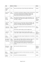
Table 1-1 Hoist Inspection Methods and Criteria
Item
Method
Criteria
Action
Functional
Operating
Mechanisms
Visual,
Auditory
Mechanisms
should be properly adjusted and should not make unusual
sou
nds when operated.
Repair or
replace as
required
Braking
System
Operation
Function
Braking distance with rated capacity should not exceed
approximately five chain links.
Repair or
replace as
required
Hooks
(surface
condition)
Visual
Should be free of significant rust, weld splatter, deep nicks, or
gouges.
Replace
Hooks (yoke
assembly)
Visual
Should be free of significant rust, weld splatter, nicks or gouges.
Holes should not be elongated, fasteners should not be loose and
there should be no gap between mating parts.
Tighten or
replace as
required
Summary of Contents for 72642
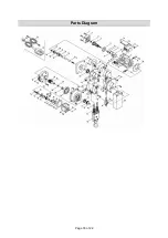
Page 16: ...Page 16 of 22 Parts Diagram ...


