background image

Page 18 of 22 


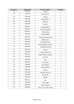
Reference 

Part Number 

Part Description 

Quantity 

32 

72642-32 

Bearing 6201Z 

33 

72642-33 

Key 

34 

72642-34 

First section gear shaft 

34-1 

72642-34-1 

First section gear shaft 

35 

72642-35 

Gear cover 

36 

72642-36 

Screws 5*20 

37 

72642-37 

Bearing 6007Z 

38 

72642-38 

Upper hook 

39 

72642-39 

Left main body sheet 

40 

72642-40 

Chain guiding wheel 

41 

72642-41 

Upper chain guiding wheel 

42 

72642-42 

Chain pawl device 

43 

72642-43 

Chain guider 

44 

72642-44 

Main body cover 

45 

72642-45 

Fixing rod of main body 

46 

72642-46 

Ring main body sheet 

47 

72642-47 

Screws 8*30 

48 

72642-48 

Chain 

49 

72642-49 

Chain bag 

50 

72642-50 

Chain stopping block 

51 

72642-51 

Latch 

52 

72642-52 

Nuts, washer 

53 

72642-53 

Chain guiding spring 

54 

72642-54 

Lower hook 

55 

72642-55 

Chain sheet iron 

56 

72642-56 

8mm latch 

57 

72642-57 

Nuts, washer 

58 

72642-58 

Chain guider 

59 

72642-59 

Gear shaft 

60 

72642-60 

Fixing base of gear shaft 

61 

72642-61 

Screws 8*16 

62 

72642-62 

Third section gear shaft 

63 

72642-63 

Key 

Summary of Contents for 72642

Page 1: ...ric Chain Hoist Owner s Manual WARNING Read carefully and understand all ASSEMBLY AND OPERATION INSTRUCTIONS before operating Failure to follow the safety rules and other basic safety precautions may result in serious personal injury Item 72642 ...

Page 2: ... that you read the entire manual to become familiar with this product before you begin using it This electric hoist is designed for certain applications only Northern Tool and Equipment is not responsible for issues arising from modification or improper use of this product such as an application for which it was not designed We strongly recommend that this product not be modified and or used for a...

Page 3: ...pecifications 4 Important Safety Information 4 Specific Operation Warnings 6 Grounding 7 Assembly Instructions 7 Before Each Use 8 Operating Instructions 12 After Each Use 13 Maintenance 14 Troubleshooting 14 Parts Diagram 16 Parts List 17 Replacement Parts 20 Limited Warranty 21 ...

Page 4: ...tions in this manual cannot cover all possible conditions or situations that could occur Exercise common sense and caution when using this tool Always be aware of the environment and ensure that the tool is used in a safe and responsible manner Do not allow persons to operate or assemble the product until they have read this manual and have developed a thorough understanding of how it works Do not...

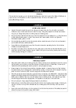
Page 5: ...rsonal injury and or property damage if contacted WARNING PERSONAL SAFETY Stay alert watch what you are doing and use common sense when operating the tool Do not use the tool while you are tired or under the influence of drugs alcohol or medication A moment of inattention while operating the tool may result in serious personal injury Dress properly Do not wear loose clothing dangling objects or je...

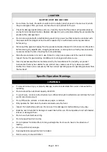
Page 6: ...torage and before re use Use only accessories that are recommended by the manufacturer for use with your product Accessories that may be suitable for one product may create a risk of injury when used with another tool Never use an accessory that has a lower operating speed or operating pressure than the tool itself Specific Operation Warnings WARNING To prevent serious injury or property damage re...

Page 7: ...y away from the user reducing the risk of electric shock See Figure A The grounding prong in the plug is connected through the green wire inside the cord to the grounding system in the tool The green wire in the cord must be the only wire connected to the tool s grounding system and must never be attached to an electrically live terminal Your tool must be plugged into an appropriate outlet properl...

Page 8: ...nstallations where the slack chain hanging from the hoist may be questionable or hazardous the use of a chain container is recommended Do not attempt to store more chain in the chain container than what is specified for the hoist or serious damage to hoist may result and hazardous conditions may be created Installing a Standard Chain Container 1 Remove both bolts from the chain container mounting ...

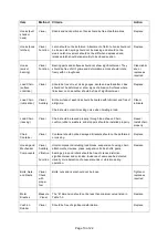
Page 9: ...ly 9 Check the operation of the hoist brake and run under light load and full load conditions Inspection Methods and Criteria This section lists items that require inspection Disassembly for further inspection would be required if frequent or periodic inspection results indicate Such disassembly and further inspection should only be performed by a certified or qualified person trained in the disas...

Page 10: ...ire surface of each link should be coated with lubricant and free of dirt grime Chain should not emit cracking noise when hoisting a load Clean lubricate Load Chain reeving Visual Chain should be reeved properly through load sheave Chain cushion rubbers washers and stoppers should be installed properly Reeve Install chain properly Chain Container Visual Container should not be damaged Brackets sho...

Page 11: ... down Repair or replace as necessary Pendant wiring Visual Wire connections to switches in pendant should not be loose or damaged Tighten or repair Pendant housing Visual Pendant housing should be free of cracks and mating surfaces of parts should seal without gaps Replace Pendant cord Visual Electrical Continuit y Surface of cord should be free from nicks gouges and abrasions Each conductor in co...

Page 12: ...s Mounting the Hoist Hang the hoist from its intended support The structure used to support the hoist must have sufficient strength to withstand several times the load amount If you are not sure of the weight the structure can hold consult a registered engineer and the local building codes Load Chain The chain should feed smoothly into and away from the hoist and hook block 1 ton If the chain bind...

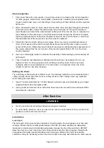
Page 13: ... treated and hardened and should never be repaired Do not use replaced chain for other purposes such as lifting or pulling Load chain may break suddenly without visual deformation For this reason cut replaced chain into short lengths to prevent use after disposal Cutting the Chain The load chain is hardened and is difficult to cut The following methods are recommended when cutting a length of new ...

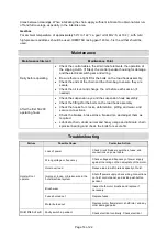
Page 14: ...ook assembly Check the fittings for the bolts on the load hook assembly Check the hooks for cracks deformation pitting and wear and secure connections Check the brakes brake stroke brake disc and adjust them as required Lubricate chain under normal and heavy usage and lubricate chain sprocket bearing and check the bolts for secure fits Troubleshooting Failure Possible Cause Corrective Action Hoist...

Page 15: ...d to within rated capacity Low voltage in hoist s power supply Determine cause of low voltage and bring to within plus or minus 5 of the voltage specified on the motor nameplate The voltage should be measured at the hoist contractor Faulty friction clutch If abnormal operation or slippage occurs do not attempt to disassemble or adjust the mechanical load brake with the friction clutch Replace the ...

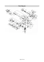
Page 16: ...Page 16 of 22 Parts Diagram ...

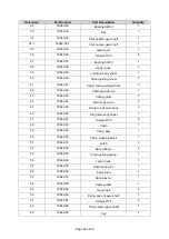
Page 17: ...3 72642 13 Screws 5 8 4 14 72642 14 Resistor 1 15 72642 15 Screws 5 8 2 16 72642 16 Bridge type rectifier 2 17 72642 17 Screws 5 16 2 18 72642 18 Rubber band 1 19 72642 19 Base of carbon brush 2 19 1 72642 19 1 Carbon 2 20 72642 20 Carbon brush cover 2 21 72642 21 Rubber washer 1 22 72642 22 Control cable socket 1 23 72642 23 Screws 3 16 3 24 72642 24 Power supply input term 1 25 72642 25 Screws 3...

Page 18: ...Chain pawl device 1 43 72642 43 Chain guider 2 44 72642 44 Main body cover 2 45 72642 45 Fixing rod of main body 4 46 72642 46 Ring main body sheet 1 47 72642 47 Screws 8 30 2 48 72642 48 Chain 1 49 72642 49 Chain bag 1 50 72642 50 Chain stopping block 1 51 72642 51 Latch 2 52 72642 52 Nuts washer 2 53 72642 53 Chain guiding spring 1 54 72642 54 Lower hook 1 55 72642 55 Chain sheet iron 1 56 72642...

Page 19: ...1 75 72642 75 Keyless gear 1 76 72642 76 Pawl brake lining 1 77 72642 77 Brake depressor lower 1 78 72642 78 Compressed spring 2 79 72642 79 Washer 1 80 72642 80 Torque limited nuts 1 81 72642 81 Brake depressor upper 1 82 72642 82 Fixing pin 1 83 72642 83 Bolt 1 84 72642 84 Click spring 1 85 72642 85 Back stopper 1 86 72642 86 Bearing 6000Z 1 87 72642 87 Gasket 1 88 72642 88 First layer gear box ...

Page 20: ...ns provided are a convenient reference to the location and position of parts in the assembly sequence When ordering parts the following information will be required item description item model number item serial number item lot date code and the replacement part reference number The distributor reserves the rights to make design changes and improvements to product lines and manuals without notice ...

Page 21: ...y claim contact Us at 1 800 222 5381 identify the product by make and model number and follow the claim instructions that will be provided The product and the purchase receipt must be provided to Us in order to process Your warranty claim Any returned product that is replaced or refunded by Us becomes our property You will be responsible for return shipping costs or costs related to Your return vi...

Page 22: ...Page 22 of 22 Distributed by Northern Tool Equipment Company Inc Burnsville Minnesota 55306 www northerntool com Made in Taiwan ...

Reviews: