ASSEMBLY INSTRUCTIONS FOR:
Page 25
11/07/00
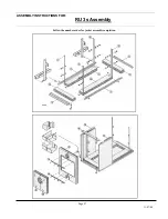
Assembly of boiler connections.
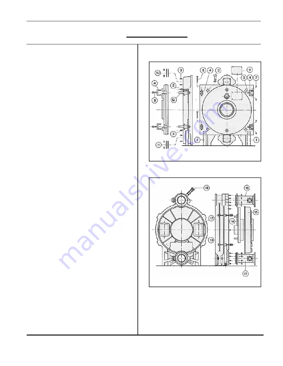
Legend
(Fig. 4.3)
1. Door
2.
Tapered centre pins
3. Door
closing
bolts
4. Channel
jacking
bracket
5. Hinge
pins
6.
Jacking bolts
7. Holding
pins
8. Jacking
bolts
9. Flange
bolts
10.
Blank flange and joint gasket
11.
Blank flange and joint gasket
12. Slotted
hinge
bracket
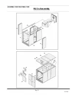
(Fig. 5.3)
12.
Small sound absorbing inserts
13. Cleaning
covers
14.
Large section of sound absorber.
15.
Flue gas collector hood
16. Flow
17. Return
18. Thermostat
sensor
pockets
Continue to pressure test as per RU 1s instructions.
ASSEMBLY INSTRUCTIONS FOR:
Fig. 4.3
Fig. 5.3
ASSEMBLY
INSTRUCTIONS
FOR:
RU 3s Assembly


