


ASSEMBLY INSTRUCTIONS FOR:
Page 11
11/07/00
Boiler Assembly Completion
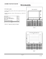
Assembly of the boiler connections
-
Fit blank flanges top and bottom at the front.
- Fit boiler flow header to the rear at the top and boiler return
header to the rear at the bottom.
Fit the 2 ½” plugs in the boiler return header
Legend
1. Hexagonal screws M12 x 35
2. Supporting Washer 13/24 x 2.5
3. Blank flanges 105
4. Rubber seal 96/61 x 5
5. Hexagonal screw M16 x 40
6. Flat washer 17/30 x 3
7. Blank
flange
170
8. Rubber seal 160/120 x 5
9. Rubber seal 152/115 x 5
10. Flat washer 17/30 x 3
11. Hexagonal nut M16
12. Hexagonal nut M16
13. Flat washer 17/30 x 3
14. Rubber seal 152/115 x 5
15. Weld neck flange NW100, ND6
16. Hexagonal screw M16 x 60
17. Hexagonal screw M12 x 55
18. Blank flange 105 or pre welded flange 105, NW65
19. Flat washer 13/24 x 2.5
20. Hexagonal nut M12
21. 2 x ½” plugs
NOTE: RU 2s details shown in Fig. 5.2 and RU 3s details in
Fig. 4.3 & Fig 5.3.
Cold Water Pressure Test
The assembled boiler block should be given a water pressure
test of 1.3 times the excess operating pressure. The test excess
pressure, however, must be at least 1 bar higher than the
operating excess pressure.
The highest test excess pressure is as follows:
-
with a normal construction 5.5 bar
-
with a multi-storey construction 7.8 bar
Assembly of boiler connections
ASSEMBLY
INSTRUCTIONS
FOR:
RU 1s Assembly