20
1. IGNITION
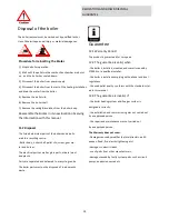
Basic display
1
2
3
4
6
5
7
8
9
11
10
13
12
1. IGNITION
Boiler controller
Control panel
The controller is used for regulating the pellet boiler opera-
tion and should be set before commissioning
The design of the control panel is shown below:
The controller has an LCD display and 6
buttons on the right side of the display.
Functions of the buttons
Increase of parameter values
Escape, boiler power off
Browse menu – go back
Browse menu – go forward
Decrease the parameter values
Enter, confirm selected parameter
Inputs
- Boiler probe (Pt 1000)
- Flue gas probe (Pt 1000)
- Domestic water probe (NTC, 10 k
Ω)
- Heat store probe (NTC, 10 k
Ω)
- Room thermostat
- Input – GSM controller
Outputs
-
Ignition system (relay,8A, NO)
- Pellet auger (relay, 5A, NO) -
Fan (PWM)
Legend
1 Time
2 Boiler operation
3 DHW temperature
4 Fan activated
5 Pump
6 Pellet auger
7 Ignition system
8 Boiler pump
9 Pre-set power output
10 Flue gas temperature
11 Current set boiler temperature
12 Program
13 Boiler operation phase
EXPLANATION OF THE DISPLAY (legend 13)
Boiler operational phase, information about the
current phase of boiler operation Boiler OFF,
First ignition-phase, Combustion-phase, Cool-
down phase, Room thermostat ,off etc.
The symbol „Boiler operation“ shows if the boil-
er is active or not.
If the boiler is set to run in a pre-programmed
operation mode, the display shows „TIME“.
The symbols in the bottom line show the opera-
tional availability of the controller outputs such
as fan, pump, auger, ignition , boiler pump and
whether they are active or not. If the symbol
shows, that component is active.
BOILER CONTROL


