


Product description
Instructions for use • KARL STORZ OR1 FUSION
®
, Rel. 1.4.2 • JEB924_EN_V1.0_02-2021_IFU_CE-MDR
13
1
2
3
5
6
8
9
10
11
12
13
14
15
16
17
4
7
18
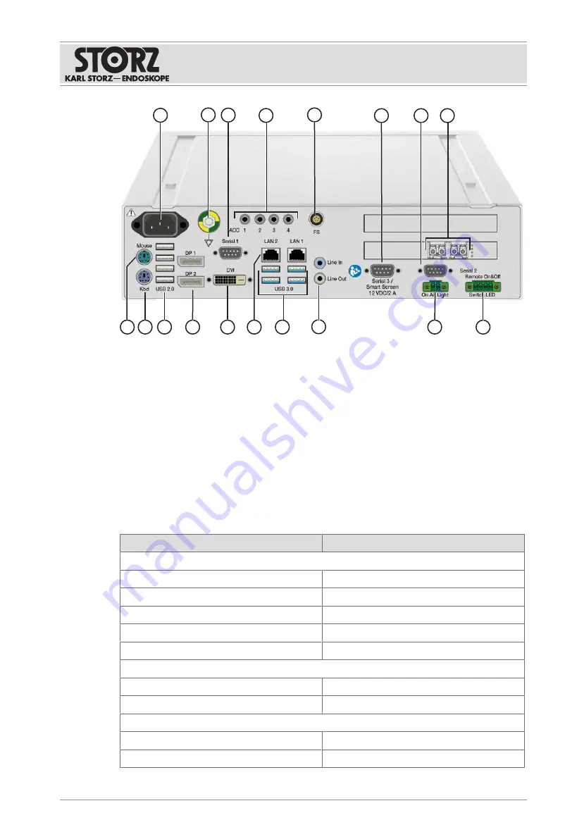
OR1 FUSION CONTROL
®
rear view
1
Power connection
10
On Air Light (Phoenix 2-pin)
2
Potential equalization connection
11
Mini jack (audio IN/OUT)
3
Serial interface (DE 9)
12
4x USB 3.0
4
4x 3.5 mini jack (camera head buttons) 13
2x LAN (RJ-45)
5
Lemo 5-pin (foot pedal)
14
Monitor (DVI)
6
Serial interfaces, smart screen (D-Sub
DE 9)
15
2x monitor (digital port)
7
Serial interface (DE 9)
16
4x USB 2.0
8
2x 10G fiber-optic interface
17
Keyboard (PS/2)
9
Remote switch (Phoenix 4-pin)
18
Mouse (PS/2)
4.3 Technical data
Description
Value
Power supply
Operating voltage
100 – 240 V
Operating frequency
50 – 60 Hz
Maximum current consumption
5 – 2 A
Electrical protection class
I
Degree of protection acc. to IEC 60259
IPX0
Housing
Dimensions (L x H x W)
355 x 74.5 x 305 mm
Weight
6 kg
System
Hard disk capacity
2 TB
Random Access Memory (RAM)
16 GB


