background image

Chapter 2.  Creating an Initial Configuration

EK–SMRA3–IG. C01

2–7

NOTE

For some operating systems, Logical Units must be sequential.
They must begin with D0 and be followed by D1, D2, D3, ..... etc.

The final step in creating the RAIDset is to enable the writeback cache. A single CLI
command enables that feature for the entire RAIDset:

SWXRC> SET D0 WRITEBACK_CACHE

SWXRC> SET D1 WRITEBACK_CACHE

Where: D0 and D1 represent the host logical units of the RAIDsets described above.

2.8

Create a STRIPEset

If you require STRIPE sets to be available to the host as Logical Units, you must now
combine disks into a STRIPEset. STRIPEsets must have at least two members, and can have
as many as fourteen. This example creates a three member STRIPEset using the ADD
STRIPESET command.

SWXRC> ADD STRIPESET STRIPE_SET_1 DISK110 DISK210 DISK310

In this example, “STRIPE_SET_1” is the name of the STRIPEset, and it is followed by a list
of the disks to be included in the STRIPEset. The names of the STRIPEsets are user
selectable. Performance of your STRIPEsets will be optimized if each STRIPEset includes
disks from different channels as shown in the example on page 2-5.

2.8.1  Initialize the STRIPEset

Before you can put the STRIPEset into service, it must be initialized.

When you initialize a STRIPEset, a chunksize must be specified. A chunksize is the number
of blocks of data that are transferred at one time. By using the default chunksize, the
controller will optimize the chunksize by selecting a number equal to the number of blocks in
one track of disk data.  We recommend using the default chunksize.

SWXRC> INITIALIZE STRIPE_SET_1 CHUNKSIZE=DEFAULT

NOTE

Valid chunksizes are 16 – 32768 blocks. You should use a larger
chunksize for applications that make a lot of I/O requests. Use a
smaller chunksize for applications that make relatively few I/O
requests, but need to move large amounts of data with each
request.

2.8.2  Add the STRIPEset as a Logical Unit

To make a STRIPEset available to the host computer, you must identify it as a host logical
unit. The unit number is a one or three digit number preceded by “D”. The unit number
identifies the controller’s target number and the STRIPEset as the Logical Unit (LUN)
connected to the target.  Units identified with controller target number 0 have a single digit
number which corresponds to LUN number.  For example, D5 would be target 0, LUN 5.
Units identified with controller targets 1, 2 and 3 use a 3 digit number.  The first digit

Summary of Contents for RAID Array 410

Page 1: ...Getting Started RAID Array 410 for HP UX Installation Guide Order Number EK SMRA3 IG C01 Digital Equipment Corporation Maynard Massachusetts...

Page 2: ...Digital Equipment Corporation makes no representation that the use of its products in the manner described in this publication will not infringe on existing or future patent rights nor do the descript...

Page 3: ...2 4 2 6 Add Disks to the Configuration 2 5 2 7 Create a RAIDset 2 6 2 7 1 Initialize the RAIDset 2 6 2 7 2 Add the RAIDset as a Logical Unit 2 6 2 7 3 Set Writeback Cache 2 7 2 8 Create a STRIPEset 2...

Page 4: ...ty of the Required Device Driver 4 2 4 1 3 Create a disktab Entry 4 3 4 1 4 Set the SCSI Bus Address of the RAID Array Controller 4 3 4 1 5 Reboot the System and Verify the Successful Installation 4 3...

Page 5: ...of this publication and their effective dates The publication part number is included in the Revision Level column with the last entry denoting the latest revision This publication supports the Storag...

Page 6: ...Chapter 1 Unpacking The SWXRA Yx RAID Array Subsystem Unpacking describes how to unpack and place the SWXRA Yx Office Expansion RAID Enclosure Chapter 2 Creating an Initial Controller Configuration U...

Page 7: ...onventions Table 2 Style Conventions Style Meaning boldface monospace type To be input by the user plain monospace type Screen text italic type For emphasis manual titles utilities menus screens and f...

Page 8: ...pin serial The major steps for installing all of the components of the StorageWorks RAID Array 410 Subsystem include the following 1 Configuring the RAID Controller using the Command Line Interface C...

Page 9: ...Performance SCSI Adapter A BN21K 05 SCSI cable three meters long with a right angle high density 68 pin connector on one end and a straight high density 68 pin connector on the other The StorageWorks...

Page 10: ...x RAID Array 410 Subsystem is designed for installation in Federal Communications Commission FCC Class A environments Before installing the SWXRA Yx make sure that adequate space is available in front...

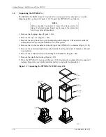
Page 11: ...top cover Figure 1 2B 3 Remove the ramp from the top of the shipping carton Figure 1 2B and set it aside for subsequent use in moving the SWXRA Yx off the pallet 4 Remove the two foam cushions from th...

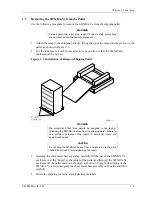
Page 12: ...on Shipping Pallet WARNING We recommend that three people be assigned to the task of unloading the SWXRA Yx array from its shipping pallet Failure to use sufficient personnel may result in personnel i...

Page 13: ...ing procedure to move the SWXRA Yx to its designated site WARNING To prevent damage to the SWXRA Yx and injury to personnel make sure to provide a clear path for the casters 1 Roll the SWXRA Yx enclos...

Page 14: ...This chapter specifies the CLI commands required to create an initial configuration for the controller See Command Line Interpreter in the SWXRC 04 RAID Array Controller User s Guide for detailed des...

Page 15: ...nfigured with a controller at ID0 SCSI target 0 and a single drive logical unit D0 Enter the following command to verify the controller s parameters SWXRC SHOW THIS_CONTROLLER FULL The controller resp...

Page 16: ...se key is INVALID then enter the following SWXRC RUN FLS and follow the menu driven program to enable the license You will need the WRITE BACK CACHE RAID5 and MIRROR License Key page that is provided...

Page 17: ...SCSI target number SWXRC SET THIS_CONTROLLER ID 0 SWXRC SET THIS_CONTROLLER PERFERRED_ID 0 Enter the following command to copy parameters to the other controller the one the terminal is not connected...

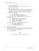
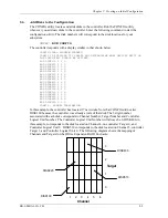
Page 18: ...4 2 0 ADD DISK430 4 3 0 ADD DISK500 5 0 0 ADD DISK510 5 1 0 ADD DISK520 5 2 0 ADD DISK530 5 3 0 ADD DISK600 6 0 0 ADD DISK610 6 1 0 ADD DISK620 6 2 0 ADD DISK630 6 3 0 CONFIG NORMAL TERMINATION In th...

Page 19: ...ZE RAID_SET_1 CHUNKSIZE DEFAULT SWXRC INITIALIZE RAID_SET_2 CHUNKSIZE DEFAULT NOTE Valid chunksizes are 16 682 blocks You should use a larger chunksize for applications that make a lot of I O requests...

Page 20: ...mple on page 2 5 2 8 1 Initialize the STRIPEset Before you can put the STRIPEset into service it must be initialized When you initialize a STRIPEset a chunksize must be specified A chunksize is the nu...

Page 21: ...you can put an individual disk into service it must be initialized SWXRC INITIALIZE DISK410 SWXRC INITIALIZE DISK510 If you require individual Disks to be available to the host as Logical Units you m...

Page 22: ...ify it as a host logical unit The unit number is a one or three digit number preceded by D The unit number identifies the controller s target number and the MIRRORset as the Logical Unit LUN connected...

Page 23: ...fourteen This example creates a two member STRIPEset using the ADD STRIPESET command SWXRC ADD STRIPESET STRIPE_MIRROR MIRROR_SET_3 MIRROR_SET_4 In this example STRIPE_MIRROR is the name of the STRIP...

Page 24: ...ical Units by using the ADD UNIT command SWXRC ADD UNIT D500 STRIPE_MIRROR NOTE For some operating systems Logical Units must be sequential They must begin with D0 and be followed by D1 D2 D3 etc The...

Page 25: ...Getting Started RAID Array 410 for HP UX 2 12 EK SMRA3 IG C01 Date__________________ LUN Uses...

Page 26: ...D400 DISK220 MIRROR_SET_3 mirrorset DISK320 STRIPE_MIRROR DISK420 MIRROR_SET_4 mirrorset DISK520 STRIPE_MIRROR DISK620 RAID_SET_1 raidset DISK100 D0 DISK200 DISK300 RAID_SET_2 raidset DISK400 D1 DISK5...

Page 27: ...Getting Started RAID Array 410 for HP UX 2 14 EK SMRA3 IG C01 Date__________________ Name StorageSet Uses Used by...

Page 28: ...The BN21K 05 SCSI cable three meters long with a right angle high density 68 pin connector on one end and a straight high density 68 pin connector on the other Refer to your system manual for addition...

Page 29: ...e following steps must be performed to successfully install the HP PB host adapter Select an available double high adapter slot Verify the setting of the SCSI ID dip switches Insert the HP PB host ada...

Page 30: ...ee Figure 3 1 Note that HP PB adapter requires one double high slot A double high slot comprises two single high slots Figure 3 2 Rear View of HP 9000 Series 800 Computer 1 Select an available double...

Page 31: ...e SCSI address of the adapter By convention the SCSI address of a host adapter is normally 7 providing it with the highest priority among the eight devices that can be attached to an 8 bit bus The swi...

Page 32: ...mponents or the board etches 2 Carefully align the host adapter up with the preformed grooves at the top and bottom of the slot 3 Gently slide the host adapter into the slot making sure that the host...

Page 33: ...re 3 6 Back of Host Computer with Host Adapter Board Installed 3 1 2 4 Connect Cable to Adapter Connector 1 Locate the cable provided as part of the RAID Subsystem Kit 2 Check the cable s straight con...

Page 34: ...meter cable between the host system and the RAID Controller Route the right angle connector end of the cable under the SWXRA Yx Subsystem enclosure and up through the front access hole nearest to the...

Page 35: ...e Module contains a battery that may have discharged since the time it was factory installed If you attempt to initiate any RAID commands when the battery in not charged unspecified results may occur...

Page 36: ...ministrator Part Number B2355 90029 Installing the disk driver on HP UX requires the following major steps Determine the interface required Section 4 1 1 Verify the availability of the required device...

Page 37: ...t of your current kernel configuration file the system will return a message showing the major number device driver name and device class If this is the case proceed to the next step If the system ret...

Page 38: ...er must be configured See Creating an Initial Configuration in Chapter 2 of this guide 1 Shutdown the HP system and ensure that all power switches on the RAID Array Control ler and on the Series 800 c...

Page 39: ...decimal entity id ok 4 2 What To Do Next The HP UX operating system has now been modified to communicate with the RAID Array Controller Refer to the System Administration Tasks manual for instructions...

Page 40: ...1 A Configuration Records Blank Forms This contains copies of the two tables used in Section 2 to record the configuration of your system If additional copies are required these tables can be reprodu...

Page 41: ...Getting Started RAID Array for HP UX A 2 EK SMRA3 IG C01 Date_____________ LUN Uses...

Page 42: ...Appendix A ConfigurationRecords Blank Forms EK SMRA3 IG C01 A 3 Date__________________ Name StorageSet Uses Used by...

Page 43: ...Getting Started RAID Array for HP UX A 4 EK SMRA3 IG C01 Date_____________ LUN Uses...

Page 44: ...Appendix A ConfigurationRecords Blank Forms EK SMRA3 IG C01 A 5 Date__________________ Name StorageSet Uses Used by...

Page 45: ...Getting Started RAID Array for HP UX A 6 EK SMRA3 IG C01 Date_____________ LUN Uses...

Page 46: ...Appendix A ConfigurationRecords Blank Forms EK SMRA3 IG C01 A 7 Date__________________ Name StorageSet Uses Used by...

Page 47: ...Getting Started RAID Array for HP UX A 8 EK SMRA3 IG C01 Date_____________ LUN Uses...

Page 48: ...Appendix A ConfigurationRecords Blank Forms EK SMRA3 IG C01 A 9 Date__________________ Name StorageSet Uses Used by...

Reviews: