background image

4


Getting Started

Getting Started

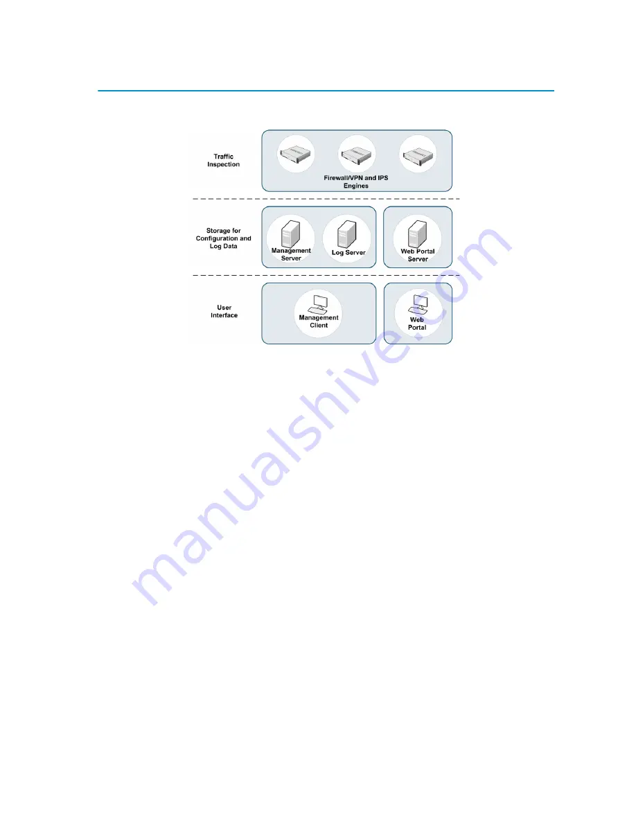
StoneGate System Components

The illustration above shows all available StoneGate components. Out of 

these, you need the following components to have an operational 

Firewall/VPN system:

1. A 

Management Server

, which stores the configuration of the 

system. In most environments, it is best to have just one common 

Management Server for all firewall and IPS engines.

2. At least one 

Log Server

 to handle and store logs and alerts (can 

be installed simultaneously on the same machine with the 

Management Server).

3. At least one 

Management Client

 that you use to connect to the 

Management Server to change settings and monitor the system.

4. The 

Firewall Engines

 that handle the actual traffic processing (in 

this case, the StoneGate appliance).

5.

Licenses

 for each component except the Management Client(s). 

Generate appliance licenses at the Stonesoft website with the 

POS (proof-of-serial-number) code attached to the appliance.

The 

Web Portal Server

 is an optional component that can be ordered 

separately.
StoneGate IPS engines can be added to the same system for unified 

management and incident handling.

Summary of Contents for StoneGate FW-5105

Page 1: ...Appliance Installation Guide FW 5105...

Page 2: ...oducts described in these materials are provided pursuant to the general terms for support and maintenance services and the related service description which can be found at the Stonesoft website www...

Page 3: ...ve a working Management Center on a separate server to bring the appliance s operational The system architecture is explained on the next page The installation of the Management Center is explained in...

Page 4: ...e installed simultaneously on the same machine with the Management Server 3 At least one Management Client that you use to connect to the Management Server to change settings and monitor the system 4...

Page 5: ...he Management Center Installation Guide and the Firewall VPN Installation Guide explain how to install the Management Center and how to configure your firewalls basic settings The Online Help of the M...

Page 6: ...hich will cause electrical shock Use extreme caution when using metal tools which can easily damage any electrical components or circuit boards they come into contact with Do not use mats designed to...

Page 7: ...rist strap designed to prevent static discharge Laser Precautions Class 1 Laser Product Operating Precautions Care must be taken to assure that the appliance cover is in place when the appliance is op...

Page 8: ...it was damaged in any way If the appliance itself shows damage file a damage claim with the carrier who delivered it Do not remove the anti tamper tapes on any part of the appliance Caution The batte...

Page 9: ...so has six LED indicators and two buttons which are explained below Front Panel Indicators The front panel has six LED indicators in the upper right corner The LEDs provide you with critical informati...

Page 10: ...rd LAN2 Ethernet interface when flashing check the port number on the back panel Indicates network activity on the onboard LAN1 Ethernet interface when flashing check the port number on the back panel...

Page 11: ...sections below before you begin the installation Choosing a setup location Decide on a suitable location for the rack unit that will hold the appliance The appliance must be situated in a clean dust f...

Page 12: ...r supply UPS to protect the appliance from power surges voltage spikes and to keep your system operating in case of a power failure Always keep the rack s front door and all panels and components on t...

Page 13: ...the appliance and the outer rails secure directly to the rack You must first install the inner rails to the appliance T To install the inner rails 1 Place the inner rail on the side of the appliance a...

Page 14: ...ear rail to the front rail by sliding the opening of the rear rail through the button 3 Measure the depth of your rack and adjust the length of the front and rear rails accordingly 4 Secure the front...

Page 15: ...o the outer rails keeping the pressure even on both sides you may have to depress the locking tabs when inserting When the appliance has been pushed completely into the rack you should hear the lockin...

Page 16: ...e one of the following Connect a monitor to the VGA and a keyboard to the PS 2 keyboard port Or connect a monitor to the VGA and a keyboard to a USB port Or connect the supplied null modem cable to th...

Page 17: ...AT 5e or CAT 6 in gigabit networks Speed Duplex Settings Network cards at both ends of each cable must have identical speed duplex settings This also applies to the automatic negotiation setting if on...

Page 18: ...if one of the power connectors fails 2 Plug the power cords into grounded high quality power strips that offer protection from electrical noise and power surges We highly recommend using an uninterrup...

Page 19: ...other cases you need a physical connection to the appliance using a monitor and keyboard or a serial cable connection from a computer with a terminal program By default the monitor and keyboard conne...

Page 20: ...Client for details If you want to check the configuration before it is activated follow the instructions in Configuring the Engine with Configuration Wizard page 21 and import the configuration manua...

Page 21: ...Configuration Wizard T To start the configuration wizard Turn on the appliance using the power on off button The engine bootup process is shown in the console and after some time the engine configura...

Page 22: ...d press ENTER 2 Select the correct timezone in the dialog that opens Note If the desired keyboard layout is not available use the best matching available layout or select US_English Note The timezone...

Page 23: ...s ENTER The Configure Network Interfaces window is displayed Configuring the Network Interfaces The configuration utility can automatically detect which network cards are in use You can also add inter...

Page 24: ...spacebar on your keyboard to select the correct interface for contact with the Management Server 4 Highlight Next and press ENTER to continue Contacting the Management Server The Prepare for Managemen...

Page 25: ...policy that allows only administration related connections and blocks everything else In the second part of the configuration you define the information needed for establishing a connection between th...

Page 26: ...ful Management Server Contact After you see a notification that Management Server contact has succeeded or the appliance has rebooted itself after configuration with a USB stick the firewall engine in...

Page 27: ...is StoneGate appliance are described below Before accessing the appliance 1 Press the power button to power off the system 2 Unplug all power cords from the system or the wall outlets 3 Disconnect all...

Page 28: ...the power supply using the handle provided 4 Replace the power supply with a new one of the same model 5 Push the power supply into the power bay until you hear a click Caution Unplug the power cord...

Page 29: ...cing appliance fans you must first open the appliance s top cover T To replace appliance fans 1 Remove the screw that secures the cover to the appliance and press the release tabs to release the cover...

Page 30: ...ng position 4 Remove the fan from the appliance and slide the new fan into the fan housing Note It is recommended that you replace all the appliance fans at the same time If one of the fans fails the...

Page 31: ...mputer 2 On the computer open a terminal with settings 9600bps 8 databits 1 stopbit no parity 3 Re start the appliance If the appliance is powered on press Enter log in and issue command reboot 4 Wait...

Page 32: ...estore Options from the boot menu 6 Type 1 and press Enter to clear the settings A confirmation prompt is shown 7 Type YES and press Enter to perform the reset If you decide to cancel the operation ty...

Page 33: ...on the activity and link status of the ports Motherboard Ports Table 4 Motherboard Port Indicators Indicator Color Explanation Activity Amber Link ok blinks on activity Link Unlit No link or the spee...

Page 34: ...ions Dispose of the appliance separately from household waste at an appropriate waste disposal facility at the end of its useful service life Table 5 Indicators in 10 Gigabit Fiber NIC Indicator Statu...

Page 35: ...rther details All documentation and our technical knowledge base is available at www stonesoft com support Copyright 2009 Stonesoft Corporation All rights reserved All specifications are subject to ch...

Reviews: