background image

45


Assembly and setting up


7    

 Assembling machine


2. Lift the knitting machine with a fork lift from the transport surface.
3. Bring the knitting machine to the site of installation.
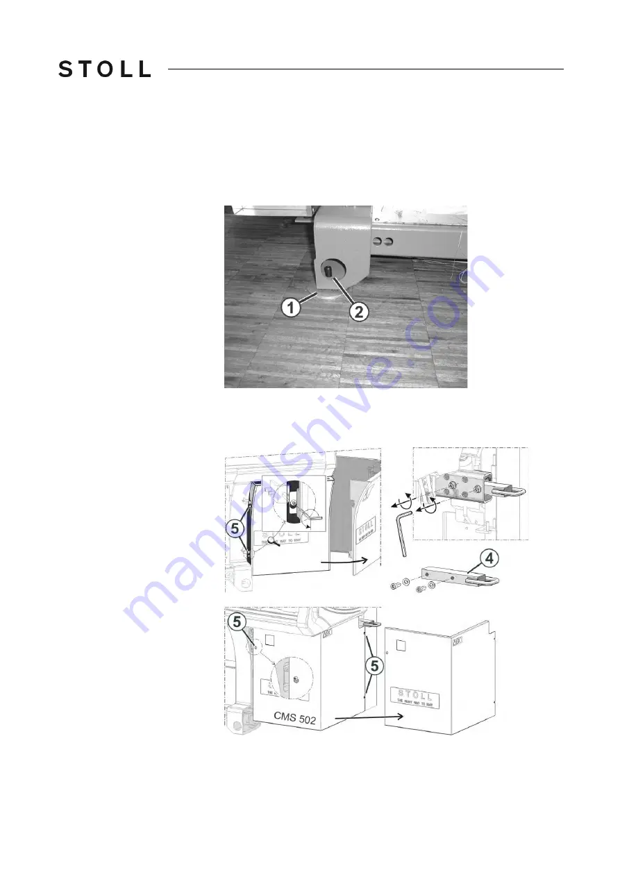
4. Lay Washers (1) from the accessories under the knitting machine foot. 

Place the washers in such a manner that the cavity comes exactly under 

the grub screw (2).

5. Setting knitting machine on the floor
6. Remove wood pieces, adhesive strips, packing film and paper.
7. Remove the screws (5). In the case of the CMS 502, loosen the screws (5).

Summary of Contents for CMS 530

Page 1: ...n manual for a safe operation of the knitting machine ID 267 886 GB Type Computer type Component type CMS 530 642 643 OKC5 0 000 000 CMS 520 C 647 OKC5 0 000 CMS 520 C 652 OKC5 0 000 CMS 502 645 646 O...

Page 2: ...ting instructions Operating system of the machine V_OKC_005 000 000_STOLL or higher H STOLL GmbH Co KG Stollweg 1 D 72760 Reutlingen Germany Our products are being developed further continuously They...

Page 3: ...for the electrical connection 17 2 6 4 Safety Instructions for the Exchange of Data 17 2 6 5 Safety Precautions for Production 18 2 6 6 Additional Safety Instructions for the Operation with Open Cover...

Page 4: ...ting up knitting machine 44 7 2 2 Connecting the knitting machine mains voltage 230 V 48 7 2 3 Connecting the knitting machine mains voltage 400 V 53 7 2 4 Connecting the knitting machine mains voltag...

Page 5: ...cuit diagram Brochure Cleaning maintenance care Pocket Card Training documents The documents are available in different languages For browsing the documentation DVD 1 Insert the DVD in the computer 2...

Page 6: ...e of queries please call the Stoll Helpline Additional information is available via the Stoll branch office or Stoll dealer in your country the Stoll Helpline Tel 49 0 7121 313 450 Fax 49 0 7121 313 4...

Page 7: ...tal protection for technical rules and for a safe and proper working The knitting machine is to be used only in a technically sound condition and as per the stipulated conditions awareness about the s...

Page 8: ...nsidered a person expert in electrical area who can assess and execute the electrical jobs assigned to him and can identify possible dangers The expert possesses the following characteristics technica...

Page 9: ...n the knitting machine practical experience Knowledge of possible dangers Selection of personnel 2 3 2 Selection of personnel The operator must ensure that only personnel authorized for the same can w...

Page 10: ...warning is given here A warning protects you from death or injuries and the knitting machine from serious damage Always read warnings carefully and observe them exactly One step action Carry out an o...

Page 11: ...864 2 Scope of validity all countries except USA and Canada A warning as per ISO 3864 2 can comprise of the following elements Elements of a warning Pictograph Explanation one or more warning indicati...

Page 12: ...274 Warning on the friction feed wheel 3 ID 244 265 Warning on the panelling of the control cabinet right and left 4 ID 244 267 Warning front cover main switch 5 ID 244 275 Warning on the base plate c...

Page 13: ...sed on the knitting machine Type Pictograph Explanation Warning indication General warning indication Dangerous electrical voltage Danger of crushing and cutting Danger from flying off mechanical part...

Page 14: ...ng Pictographs used on the knitting machine Warnings in the documentation Command Wear safety glasses Disconnect mains supply Wear hair protection gear Wait till all LEDs on the control cabinet are of...

Page 15: ...signal word red orange yellow blue Text comprises of Type and source of danger Possible outcomes Measures for protection against danger and prohibitions Example DANGER Life threatening high voltage E...

Page 16: ...other tangible assets No one may remain inside the machine Risk of death Observe the start up and shut down procedures and the indicators Before starting up or setting the machine in motion make sure...

Page 17: ...lectrical connection Type of risks Measures Danger to life during work on the electrical assembly of the machine Get the machine connected by an electrician Note technical data Safety Instructions for...

Page 18: ...and hair strands Wait for the feed wheel to stop moving after stopping the machine Health hazard by fibers dust and fumes Special caution is to be observed while knitting of yarns that cause health h...

Page 19: ...production speed After the reversal point the carriage can move at higher speed if it is set up that way in the knitting program Close the covers Do not deactivate the MSECCO check box Operation with...

Page 20: ...Recommendation In order to avoid any dust being deposited on the inaccessible points of the machine we recommend that the dust should be vacuum cleaned and the machine not to be cleaned by compressed...

Page 21: ...ing devices and the additional needle beds Always stop the machine during an intervention Move carriage step by step or at creep speed see operating instructions Danger of crushing and suction by the...

Page 22: ...er of chemical burns during contact with oil grease and other chemical substances Wear protective gear e g safety glasses gloves Observe the country specific laws and regulations Observe the manufactu...

Page 23: ...of safely and with minimum environmental impact Observe the country specific laws and regulations Observe the manufacturer s specifications safety data sheet Reason Measures Pictograph Safety precaut...

Page 24: ...he machine Close the covers Further information Checking protective devices 75 Safety instructions for dismantling work dismantling Batteries are sensitive to mechanical damages Handle with care Dange...

Page 25: ...he electrical assembly of the machine Get the machine disconnected from the mains supply by an electrician Health hazard When working with oil and grease pay attention to the safety regulations safety...

Page 26: ...ight A B C D E F G Weigh t kg Dynamic weight kg CMS 933 510 106 205 270 244 120 33 5 2060 700 CMS 830 S 403 91 205 239 218 82 25 1640 720 CMS 830 C k w 403 91 205 239 213 82 25 1690 740 CMS 822 403 91...

Page 27: ...movement of the carriage causes the dynamic loads listed above to occur at the set screws Dimensions weight and dynamic weight Dimensions weight and dynamic weight Electrical data A Width B Depth C H...

Page 28: ...f the knitting machine Before connecting the machine check the mains voltage available on site It is generally not admissible to connect electrical or electronic components of other makes to the machi...

Page 29: ...E 3 5 174 E 4 199 E 5 E 2 5 2 B 224 249 359 419 479 E 7 E 3 5 2 314 349 503 587 671 E 8 359 399 575 671 767 E 5 2 449 499 719 839 959 E 10 C 449 499 719 839 959 E 12 E 6 2 539 599 863 1007 1151 E 14 E...

Page 30: ...must be carried out 1 Clean the knitting machine thoroughly 2 Lubricate knitting machine 3 When the knitting machine is transported to another place the transport locks must be applied 4 All bare met...

Page 31: ...0 HP E7 2 The machines of the CMS 5xx HP series emit a sound pressure level which is not higher than the specified values under comparable conditions Applied standards ISO CD 9902 Textile machine regu...

Page 32: ...No Label 1 Signal light green yellow 9 Engaging rod red 2 Yarn control units 10 Fabric take down main take down auxiliary take down comb take down belt take down 3 Bobbin board with bobbin 11 Fabric c...

Page 33: ...knitting machine 4 Front side Inner view Inner view of the knitting machine Inner view of the knitting machine No Label No Label 1 Carriage 4 Yarn Carrier 2 Front needle bed 5 Yarn carrier rod 3 Left...

Page 34: ...g machine Lateral view right Lateral view right 4 2 Lateral view right Right lateral view Right lateral view No Label No Label 1 Yarn control unit 4 Lateral yarn tensioner 2 Yarn guide device 5 Latera...

Page 35: ...4 3 Rear side Rear side without rear panel segments Rear side without rear panel segments No Label No Label 1 Carriage 5 Fluff absorption 2 Rear Needle Bed 6 Control unit on the right 3 Trailing cabl...

Page 36: ...ly stopped However the machine data are not lost as they are saved with a battery This takes approx 60 seconds In the process messages appear on the touch screen Once the process has been completed th...

Page 37: ...2 Engaging rod Positions of the engaging rod 5xx Engaging rod Engaging rod 1Carriage stopped 2reduced speed 3normal speed The carriage assembly and therefore also knitting is started and stopped with...

Page 38: ...ht 5xx Signal light Signal light The signal light 1 displays the operating status of the knitting machine Depending on the machine type the signal light is mounted either on the left or on the right m...

Page 39: ...s which occur seldom e g hardware errors are shown with a common pictograph Stop motion pictographs EP net belt take down Pictographs for the display of stop motions Pictographs Cover on the left Cove...

Page 40: ...prox 60 seconds after this the main switch gets rotated to 0 The alarm signal can be switched on and off standard setting off Belt take down Friction feed wheel on the left Friction feed wheel on the...

Page 41: ...ol device Lamps on the yarn control device Lamps on the yarn control device In the case of a yarn breakage or yarn end the yarn break control of the yarn control device switches off the knitting machi...

Page 42: ...between the knitting machines for Operating the machine Removing the fabrics from the machine do not put up the machine underground Having tools and aids ready 7 1 2 Having tools and aids ready The k...

Page 43: ...ing the knitting machine e g fork lift The relevant country specific laws and regulations are to be observed when transporting with a ground conveyor e g fork lift Ground conveyor observe the safety i...

Page 44: ...y on both the machine feet or on the crossheads Setting up knitting machine 1 Remove the screwing of the knitting machine to the transport base DANGER Heavy knitting machine Danger of injury for perso...

Page 45: ...the site of installation 4 Lay Washers 1 from the accessories under the knitting machine foot Place the washers in such a manner that the cavity comes exactly under the grub screw 2 5 Setting knittin...

Page 46: ...move easily since the safety nut is self locking 11 Unscrew the distance bolt 7 12 Screw the screw 5 into the holder until it protrudes on the back side of the holder and the safety nut can completely...

Page 47: ...pots for transport locks Fixing spots for transport locks Transport lock for 1 Carriage 5 Cover at comb take down 2 Touch screen 6 Comb Take down 3 Drive 7 Comb take down 2 pieces for CMS 7xx and CMS...

Page 48: ...ected by an electrician Country specific laws and regulations are to be followed Operating the knitting machine with a generator If the knitting machine is operated with a generator make sure that the...

Page 49: ...is switched off 0 The mains supply to the machine is unplugged currentless DANGER Life threatening high voltage Electrical shock may cause death or serious injuries Deenergize on site mains supply 1...

Page 50: ...ses of the operational mains supply must be distributed evenly on L1 L2 and L3 if available 4 Make sure that the operational mains supply is loaded evenly mains symmetry You will find the connection v...

Page 51: ...pen the main switch For this loosen the 4 screws and remove the cover of the main switch 8 Connect the plug 4 on the right side 9 Close the main switch 10 Close the cover at the right control cabinet...

Page 52: ...fluff absorption can be damaged if the mains frequency is not adapted The fluff absorption is overloaded if it is not adapted to the mains frequency Adapt the fluff absorption to the mains frequency 1...

Page 53: ...trician Country specific laws and regulations are to be followed Operating the knitting machine with a generator If the knitting machine is operated with a generator make sure that the voltage supplie...

Page 54: ...main switch is switched off 0 The mains supply to the machine is unplugged currentless DANGER Life threatening high voltage Electrical shock may cause death or serious injuries Deenergize on site main...

Page 55: ...nnected 6 Close the plug 2 and connect it to the main switch Mains supply 3 Example for mains symmetry Connection variant Plug 2 A B C L1 L1 L2 L3 L2 L2 L3 L1 L3 L3 L1 L2 N N N N PE PE PE PE L3 is not...

Page 56: ...tch For this loosen the 4 screws and remove the cover of the main switch 8 Remove the plug 4 from the left side and connect it on the right side 9 Close the main switch 10 Close the cover at the right...

Page 57: ...orption can be damaged if the mains frequency is not adapted The fluff absorption is overloaded if it is not adapted to the mains frequency Adapt the fluff absorption to the mains frequency 1 Open the...

Page 58: ...ian Country specific laws and regulations are to be followed Operating the knitting machine with a generator If the knitting machine is operated with a generator make sure that the voltage supplied by...

Page 59: ...is switched off 0 The mains supply to the machine is unplugged currentless DANGER Life threatening high voltage Electrical shock may cause death or serious injuries Deenergize on site mains supply 1...

Page 60: ...that the operational mains supply is loaded evenly mains symmetry You will find the connection variants A B C in the above table 5 The terminal for the protective conductor PE must be connected Poten...

Page 61: ...Open the main switch For this loosen the 4 screws and remove the cover of the main switch 8 Connect the plug 4 on the left side 9 Close the main switch 10 Close the cover at the right control cabinet...

Page 62: ...absorption The fluff absorption can be damaged if the mains frequency is not adapted The fluff absorption is overloaded if it is not adapted to the mains frequency Adapt the fluff absorption to the m...

Page 63: ...ompletely on delivery of the machine Plug in battery pack The main switch is switched off 1 Open the cover on the control unit 2 Plug in battery pack 3 Close the cover Mounting the yarn guide device C...

Page 64: ...to 0 and secured against being switched on again 1 Open the lateral safety doors and loosen the screws 1 on both sides of the machine Supports for the yarn guide device Supports for the yarn guide de...

Page 65: ...this description depending on the machine type type of machine scope of supply special equipment 1 Removing transport locks 2 2 Remove the screws 3 on the left and right sides of the machine 3 Mount...

Page 66: ...sories needs only be connected and screwed into place Signal light Signal light Carefully tighten the fastening screw of the signal light to prevent the plastic holder from being damaged The main swit...

Page 67: ...wheel Mounting the friction feed wheel DANGER Life threatening high voltage Electrical shock may cause death or serious injuries Set machine main switch to 0 Secure the machine against being switched...

Page 68: ...simultaneously also a message indicating that time and date are not correct 3 Tap the OK key 4 Adjust the date A C and the time D with the help of the arrow keys 5 Save the settings and return to the...

Page 69: ...of the machine to 1 2 Tap on the Warm start key 3 Call up the Service menu from the Main menu 4 Call up the Reference runs window Reference runs window Reference runs window 5 Tap the S key in the Dir...

Page 70: ...overview Carriage in the needle bed position the covers were opened for a better overview 8 Open covers 9 Lay the spirit level on the support surfaces on the left side of the needle bed 10 Align the...

Page 71: ...r the spirit level on the right CMS 502 12 Align the knitting machine with the grub screws For the subsequent mounting activities the carriage remains in the needle bed until the section Carry out ref...

Page 72: ...n as follows Main menu Service Reference runs The carriage is located on the left side within the needle bed 1 In the Reference run carriage field tap the SR key DANGER Danger by moving carriage Dange...

Page 73: ...e machine switched on for at least 6 hours in order to charge the accumulators fully Glue on measuring tape 7 4 Glue on measuring tape The measuring tape is used to check the fabric length on the mach...

Page 74: ...ng the carriage to an immediate standstill In order to stop the movement of the carriage immediately carry out one of the following functions 1 Press the engaging rod 1 downward 2 Open covers 2 3 Open...

Page 75: ...ous injury If a protective device does not stop the machine it must be stopped for safety reasons and secured against being started up again Repair must be carried out immediately DANGER Opened covers...

Page 76: ...e carriage pulls out Open cover The carriage must be stopped immediately The engaging rod falls to zero position simultaneously Repeat this process for each cover Lateral safety doors 3 Pull engaging...

Page 77: ...window from the main menu and tap the S key Pull engaging rod to highest position The carriage moves towards left The carriage must stop shortly before reaching the bumper The limit switch triggers th...

Page 78: ...r again To confirm the calibration tap the key Condition The carriage has stopped Call up the Comb take down window and tap the key in waiting position The comb take down moves upward Wait briefly 2 3...

Page 79: ...79 Assembly and setting up 7 Checking protective devices...

Reviews: