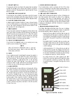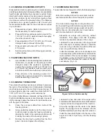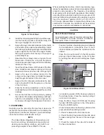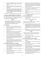
18
IMPORTANT:
Before making changes to any settings, record
the original values. If the setting changes do not
achieve desired results, return settings to their
original values.
A.
Press and hold the SEL button for 8 seconds. While
still holding the SEL button, press the up arrow
button (
). The LCD Screen will read DISPLAY.
B.
Release both buttons.
C.
Press the left arrow button (
) to get to the correct
menu (Basic, Advanced, or Storage).
D.
Press the up arrow button (
) to navigate to the
value that needs to be changed.
E.
Press the SET button to enter the edit mode.
F.
Press the up arrow button (
) to change the
setting.
G.
Press the SET button to save the setting and exit
the edit mode.
H.
Press the up arrow (
) and the left arrow (
)
buttons to navigate through the rest of the settings
as needed.
I.
When all changes have been completed, press
the up arrow button (
) from ExitMenu to return
to the current mode display.
4.5
READINGS (SERVICE PERSONNEL
ONLY)
The IntelliTec control continuously monitors and records
temperatures, voltages, amps, and error code details.
Each reading is benefi cial to service personnel when
troubleshooting.
DISPLAY READINGS
Following are the readings available under the DISPLAY
menu:
Cabinet
The temperature of the cab is constantly monitored
by the IntelliTec control.
Cycles (count)
This reading counts down the number of cycles
in the current “Serve Mode”. The starting value
is dependant upon the Cycles setting on the
IntelliTec control.
°F and amps
Suction line temperature on the freezing cylinder
and drive motor amps are available on the same
screen to assist with setup and troubleshooting.
Aux. Temp (°F)
This reading provides the ambient temperature
around the IntelliTec control board.
Supply V (VAC)
A calculated input voltage is recorded.
ERROR CODE READINGS
The following details are recorded under the ERRCODES
menu for each of the last 25 error codes received:
Err1 (hours)
A numerical count of the last 25 error codes is
recorded. When the 26th error has occurred,
the earliest error code is erased. A timer also
begins when an error occurs. The timer records
the number of hours since the error occurred. If
power to the machine is interrupted, the timer will
stop until power has been restored.
°F and amps
The suction gas temperature on the freezing
cylinder and the drive motor amps are recorded
at the time of the error.
Aux. Temp (°F)
Ambient temperature of the IntelliTec control board
is recorded at the time of the error.
Str (°F)
The storage temperature is recorded at the time
of the error.
VAC and Mode
A calculated input voltage and mode at which
the error occurred are recorded. Following are
descriptions of each mode:
Mode
Description
0
Start of freezing cycle
1
Compressor and drive motor on
2
Stir
Cycle
3
Compressor
off
4
“Standby
Mode”
5
“Sleep 1 Mode”
6
“Sleep 2 Mode”
7
“Clean
Mode”
8
Startup
9
Storage only refrigeration
10
Freezing cycle is shut down
11
Door safety switch triggered
12
High pressure cutout
Up Time (hours)
This value is a record of the total time the machine
has been in service. If power is interrupted, the
timer will stop until power is restored. This timer
does not reset.

