background image

14

Old mix, or mix that has been stored at too high a tempera-
ture, can result in a fi nished product that is unsatisfactory. 
To retard bacteria growth in dairy based mixes, the best 
storage temperature range is between 33° to 38°F (0.5° 
to 3.3° C).

3.12 OPERATION OF MIX PUMP

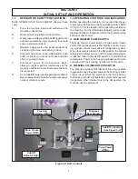
The mix pump switch is located on the lower part of the 
front panel. When a pump switch is placed in the ON posi-
tion, the mix pump motor will start pumping mix into the 
freezing cylinder. When the set pressure is reached, the 
mix pump will shut off automatically. When the switch is 
placed in the OFF position, the mix pump will not operate.

NOTE

The mix pump motor is equipped with an internal 
overload that will “trip”, disabling the pump when 
the motor is overloaded. Consult the trouble shoot-
ing section for corrective information. The internal 
overload will automatically reset after cooling. If 
the condition continues, contact a qualifi ed service 
person.

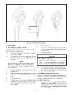
A. 

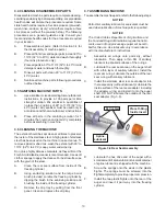
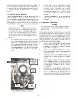
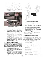
Mix Operation: The peristaltic mix pump contains 
one continuous mix pump hose. When looking at 
the face of the peristaltic mix pump, the left side 
of the hose is the mix intake or pickup. The right 
side of the hose is the mix discharge. Mix is drawn 
up the pickup side of the hose and transferred 
through the discharge side to the machine (Fig. 
3-9).

B. 

Air Operation: The air compressor operates 
whenever the peristaltic mix pump is running. 
Air enters through a check valve on the piston 
downstroke. The air is discharged through a 
second check valve, on the piston upstroke. The 
air and mix join at the tee and then travel to the 
machine.

C. 

The overrun adjustment is preset at the factory. 
If an adjustment becomes necessary, refer to 
Section 4.

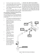
3.13 MIX PUMP CLEANING

NOTICE

Any cleaning procedure must always be followed 
by sanitizing before fi lling machine with mix. (Refer 
to section 3.3)

The mix pump is approved for CIP (clean in place). It is 
thoroughly cleaned when the detergent solution is pumped 
through the machine. We recommend completely disas-
sembling the pump and disconnecting tubing every 14 
days for inspection of parts to confi rm the CIP has been 
properly performed. If any residue is detected, clean or 
replace those parts as outlined below.

A. 

Place the Main Power OFF/ON and Freezing 
Cylinder OFF/ON switches in the ON position 
and press the CLEAN button. Allow the auger to 
agitate for 5 to 10 minutes.

B. 

Remove the suction tube from the mix container. 
Open the spigot to remove the mix remaining in 
the freezing cylinder.

C. 

Pump 2 gallons (7.5 liters) of potable water through 
machine until the water coming out of the spigot 
is clear.

D. 

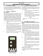
Pump 2 gallons (7.5 liters) of 90° to 110°F (32°C 
to 43°C) detergent solution through the machine. 
The use of soft water is recommended, along with 
dishwashing detergents such as “Joy,” “Dawn,” 
or equivalent.

E. 

Place the mix pump switch in the OFF position. 
Open the spigot to relieve the remaining pressure.

F. 

Press the CLEAN button to stop the auger and 
place the Main Power OFF/ON and Freezing 
Cylinder OFF/ON switches in the OFF position.

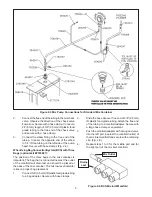
Figure 3-9 Mix Pump Hose Routing

Air Line

Mix 

Intake

Mix

Discharge

3-way 

Tee

Air/mix to 

Freeezing 

Cylinder

Summary of Contents for O411

Page 1: ...Model O411 OPERATORS MANUAL Manual No 513626 Rev 3...

Page 2: ......

Page 3: ...built prior to date of change DO NOT ATTEMPT to operate the machine until instructions and safety precautions in this manual are read completely and are thoroughly understood If problems develop or q...

Page 4: ...ecific safety information the following safety defini tions are provided to assist the reader The purpose of safety symbols is to attract your at tention to possible dangers The safety symbols and the...

Page 5: ...ting Controls and Indicators 7 3 3 Disassembly of Machine Parts 9 A Disassembly of Front Door 9 B Disassembly of Auger 9 3 4 Cleaning Disassembled Parts 10 3 5 Sanitizing Machine Parts 10 3 6 Cleaning...

Page 6: ...8 Overrun Adjustment 20 4 9 Mix Pump Hose Reposition 21 4 10 Mix Pump Hose Replacement 21 4 11 Cab Temperature Adjustment 22 4 12 Drive Belt Tension Adjustment 22 4 13 Condenser Cleaning Air Cooled M...

Page 7: ...o operate with almost any type of commercial soft serve or non dairy mixes available including ice milk ice cream yogurt and frozen dietary desserts This manual is designed to assist qualified service...

Page 8: ...hase 208 240 VAC 60Hz running amps 15A connection type NEMA6 20P power cord provided Compressor 13 000 Btu hr Scroll Compressor Drive Motor 3 4 hp Air Flow Air cooled units require 3 7 6 cm air space...

Page 9: ...lation must be completed by a qualified electrician refrigeration specialist Incorrect installation may cause personal injury severe damage to the machine and will void fac tory warranty Installation...

Page 10: ...hose clamp Be careful not to twist the mix hose 7 Turn the pump on 8 Allow the remaining 6 15cm of tubing to feed through pump until the hose adapter prevents further feeding 9 Turn the pump off CAUTI...

Page 11: ...d nearest the outlet of the manifold will drain last and should be placed at the back of the mix container The mix low level indicator relies on proper bag placement 1 Connect3 8 9 5mm IDplasticfoodgr...

Page 12: ...mp 3 Push the manifold adapter with spring and valve into the left port nearest the manifold outlet of the mix inlet manifold and secure with retaining clip See Figure 2 5 4 If using two mix bags repe...

Page 13: ...to Figure 3 1 for the location of the operating controls on the machine For the information regarding error codes displayedonthecontrolpanel refertothetroubleshooting section of this manual A MAIN FR...

Page 14: ...the Freezing Cylinder OFF ON switch to the OFF position or press the CLEAN button again If the machine is left in CLEAN for more than 20 minutes an error code E4 will be displayed on the display pane...

Page 15: ...nt door 3 Remove the front door by pulling it off the studs 4 Remove the air bleed valve by unscrewing the knob while holding the valve stem from behind Remove the compression spring and push the air...

Page 16: ...Use a soft cloth or sponge to apply the cleaner For best results wipe with the grain of the steel A Clean the rear seal surface from inside of the freezing cylinder B Using sanitizing solution and the...

Page 17: ...and Drug Administration require that all cleaning and sanitizing solutions used with food processing equipment be certified for this use When sanitizing the machine refer to local sanitary regu lation...

Page 18: ...row button once The display will read BASIC 10 Press the up arrow button once The display will read CutOut amps 11 Press the SET button A cursor will start blinking under the far right digit 12 Change...

Page 19: ...pigot to allow the mix to flush out about 8 ounces 0 23 liters of sanitizing solution and liquid mix G Open the air bleed valve on the front door by pressing and holding Hold the valve open until the...

Page 20: ...rough a second check valve on the piston upstroke The air and mix join at the tee and then travel to the machine C The overrun adjustment is preset at the factory If an adjustment becomes necessary re...

Page 21: ...if applicable as an assembly from the mix container C Completely disassemble the hose assembly and the check valve Fig 3 10 Place hoses tee checkvalveassembly andpickuphoseadapterin 90 to 110 F 32 C...

Page 22: ...16...

Page 23: ...the control panel are disabled Follow the instructions below to lock the control panel A Press and hold the PUSH TO FREEZE button for at least 5 seconds B While still holding the PUSH TO FREEZE butto...

Page 24: ...ne temperature on the freezing cylinder and drive motor amps are available on the same screen to assist with setup and troubleshooting Aux Temp F This reading provides the ambient temperature around t...

Page 25: ...of the refrigerant gas in the evaporator at the front of the freezing cylinder Changingthissettingchangesthetemperatureat which the freezing cycle starts This value along with the CutOut value determ...

Page 26: ...g Cab Off will not be shown on the IntelliTec menu Cab On If the Refriger value is set to Cabinet and the temperaturesensorinthecabinetfails thissetting determines the length of the refrigeration cycl...

Page 27: ...e any pressure by opening the spigot C Grasp the pickup hose end of the mix pump hose with one hand and turn the pump on Pull down on the pickup hose end until 12 to 14 inches of tubing has fed throug...

Page 28: ...SEL button press the up arrow button The LCD Screen will read Display B Release both buttons C Press the left arrow button three 3 times to navigate to the Storage menu D Press the up arrow button onc...

Page 29: ...tely B Monthly checks 1 Check drive belts for wear and tighten belts if necessary Refer to section 4 12 2 Check the condenser filter for dirt Refer to section 4 13 4 15 EXTENDED STORAGE Refer to the f...

Page 30: ...24...

Page 31: ...rally caused by very low mix levels in the machine s mix container or from product breakdown Another common cause results from a restriction preventing mix from entering the freezing cylinder Check th...

Page 32: ...the error persists contact your Authorized Stoelting Distributor for further assistance Error Code 9 High Pressure Cutout High Pressure Cutout Errors E9 are usually caused by a dirty or inefficient c...

Page 33: ...rrun setting 2 Raise overrun See Section 4 8 3 Low pump pressure 3 Check pump pressure 4 Large air pocket in barrel 4 Purge air from barrel 5 Auger turning counter clockwise 5 Change rotation to clock...

Page 34: ...F DRAW 2 3 PINTS TO REDUCE SYSTEM PRESSURE TO ZERO TURN PUMP ON PURGE REMAINING AIR IN MIX BAG AND PICK UP HOSE IMPORTANT Before connecting the pick up hose to the mix bag remove as much air from the...

Page 35: ...ing Distributor Dispensed product air pops 1 Overrun setting too high 1 Decrease overrun setting 2 Mix pump hose service life is exceeded 2 Reposition replace mix pump hose 3 Overdrawing the machine s...

Page 36: ...30...

Page 37: ...Parts 2 324509 Decal Cleaning Instructions 1 324566 Decal Wired According To 1 324584 Decal Adequate Ventilation 3 2 324594 Decal Attention Heat Sensitive 1 324686 Decal Danger Automatic Start 1 3247...

Page 38: ...2 624678 O Ring Rear Seal Rear Seal Adapter Black 5 Pack 2 625133 O Ring Front Door Red 1 667868 Seal Rear Auger Orange 1 694200 Spring Air Bleed Valve 1 694255 Spring Auger Flight 5 744273 Tray Drip...

Page 39: ...g 1 4 ID Clear Air Line 25 Increments Per Inch Cab 13 756079 Tubing 3 8 ID Clear Mix Line 25 Increments Per Inch Cab 24 756088 Tubing 1 2 ID Clear Mix Line 25 Increments Per Inch Cab 6 756204 Tubing 1...

Page 40: ...34...

Page 41: ...bligations remedies are subject to the conditions that Buyer a signs and returns to Stoelting upon installation the Checklist Warranty Registration Card for the affected equipment b gives Stoelting pr...

Reviews: